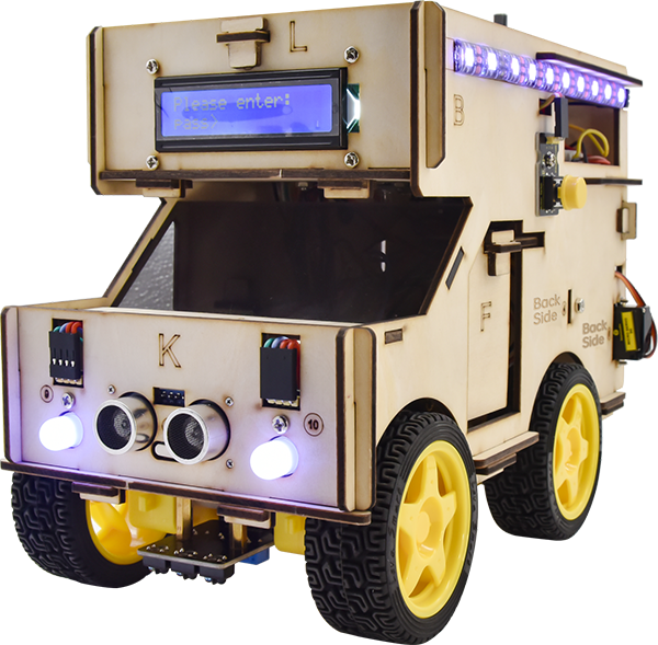
KS0507 Keyestudio Smart Motorhome Kit
Read me frist
Download the APP, Code and library from the link: https://fs.keyestudio.com/KS0507
1. Description:
When it comes to programming, many think it difficult. However, KEYES group issues a smart motorhome kit to cope with this problem.
This is a low-cost, easy-to-build and open source programming kit. In fact, it integrates a smart home and a robot car. You can absorb the knowledge of programming like electronics, control logic, computing and science from practical installation.
In compliance with the tutorial, you can create your own robot by boards, slot connection and wiring.
It also has a temperature humidity sensor and an LCD display except LED, line tracking sensor, ultrasonic sensor, Bluetooth module and motor driving modules. Furthermore, the detailed projects will guide you to learn the working principle of sensors and modules.
If interested in STEM and code programming, you can customize your smart motorhome by altering code and adding extra modules.
That sounds entertaining, right? Let’s get started!
2. Features:
Multi-purpose function:obstacle avoidance, line tracking, Bluetooth control, ultrasonic follow, smart sensation and so on.
Easy to build:Slot connection and without soldering circuit Novel style:Adopt strong wood board, acrylic board, RGB and lcd1602 modules.
High extension:configure motor driving chip, preserve IIC, UART and SPI port and expand other sensor and module.
Basic programming learning:use C language and code
3. Specification:
Working voltage: 5v
Input voltage: 7-12V
Maximum output current: 3A
Maximum power dissipation: 15W
Motor speed: 200 rpm (4.5V)
Motor driving form: TB6612 chip drive
Ultrasonic sensing angle: <15 degrees
Ultrasonic detection distance: 2cm-400cm
Bluetooth remote control distance: 50 meters (measured)
Bluetooth APP control: support Android and iOS system
4. Kit list:
Remember to check if the components received are in line with the following product list when you getting this kit.
# |
Picture |
Model |
QTY |
|---|---|---|---|
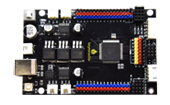
1 |
|
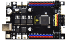
Keyestudio MEGA 2560 Smart Development Board |
1 |
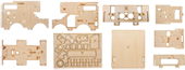
2 |
|
9 Pcs Wooden Boards |
1 |
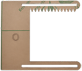
3 |
|
Acrylic Board O |
1 |
4 |
|
Acrylic Board P |
1 |
5 |
|
Keyestudio 9G 180°Servo |
3 |
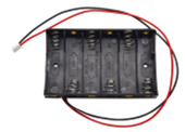
6 |
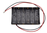
|
6-Slot AA Battery Holder |
1 |
7 |
|
4*4 Matrix Array Membrane Keypad |
1 |
8 |
|
Keyestudio I2C1602 LCD Display Module |
1 |
9 |
|
HC-SR04 Ultrasonic Sensor |
1 |
10 |
|
Keyestudio Quick Connectors Line Tracking Sensor |
1 |
11 |
|
Keyestudio TEMT6000 Ambient Light Sensor |
1 |
12 |
|
Keyestudio Steam Sensor |
1 |
13 |
|
Keyestudio DHT11 Temperature and Humidity Sensor |
1 |
14 |
|
Keyestudio Analog Gas Sensor |
1 |
15 |
|
Keyestudio Power Amplifier Module |
1 |
16 |
|
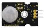
Keyestudio PIR Motion Sensor |
1 |
17 |
|
Keyestudio Full Color LED |
2 |
18 |
|
Keyestudio HM-10 Bluetooth Module |
1 |
19 |
|
Keyestudio Digital Push Button |
1 |
20 |
|
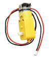
4.5V 200r Motor |
4 |
21 |
|
Car Wheels |
4 |
22 |
|
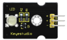
Keyestudio White LED Module |
1 |
23 |
|
Keyestudio Analog Rotation Sensor |
1 |
24 |
|
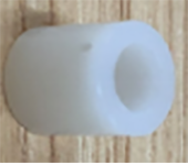
ABS White Insulation Column |
14 |
25 |
|
Aluminum Mounts |
4 |
26 |
|
M3*8MM Round Head Screws |
32 |
27 |
|
M3*10MM Round Head Screws |
6 |
28 |
|
M3*12MM Round Head Screws |
5 |
29 |
|
M3*20MM Round Head Screws |
2 |
30 |
|
M3*30MM Round Head Screws |
10 |
31 |
|
M3 Nickel Plated Nuts |
35 |
32 |
|
M3 Self-locking Nuts |
6 |
33 |
|
M2*10MM Round Head Screws |
3 |
34 |
|
M2*16MM Round Head Screws |
5 |
35 |
|
M2 Nickel Plated Nuts |
8 |
36 |
|
M1.4*8MM Round Head Screws |
6 |
37 |
|
M1.4 Nickel Plated Nuts |
6 |
38 |
|
M1.2*4MM Round Head Self-tapping Screws |
14 |
39 |
|
M3*12MM Flat Head Screws |
3 |
40 |
|
M3*10MM Copper Pillar |
3 |
41 |
|
M3*20MM Copper Pillar |
3 |
42 |
|
3.0*40MM Screwdriver |
1 |
43 |
|
2.0*40MM Screwdriver |
1 |
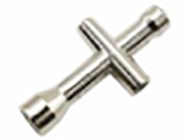
43 |
|
Cross Wrench |
1 |
44 |
|
AM/BM USB Cable |
1 |
45 |
|
Winding Pipe |
1 |
46 |
|
3*100MM Black Ties |
4 |
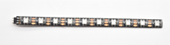
47 |
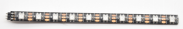
|
Full Color WS2812B LED Light Strip with 5V 5050 Light Beads |
2 |
48 |
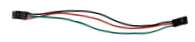
|
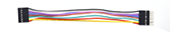
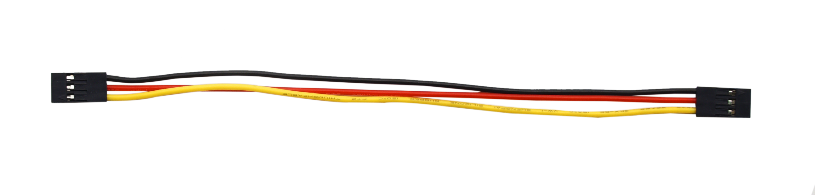
15cm 3pin F-F 26AWG Dupont Line |
2 |
49 |
|
20cm 3pin F-F 26AWG Dupont Line |
6 |
50 |
|
15cm 8pin M-F 26AWG Dupont Line |
1 |
51 |
|
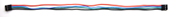
35cm 4pin F-F 26AWG Dupont Line |
2 |
52 |
|
35cm 4pin F-F 26AWG Dupont Line |
1 |
53 |
|
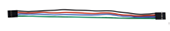
20cm 4pin F-F 26AWG Dupont Line |
2 |
54 |
|
40cm 5pin XH2.54 to PH2.0 26AWG Dupont Line |
1 |
55 |
|
15cm 3pin F-F 26AWG Dupont Line |
2 |


5. Getting Started with Arduino
(1).Installing Arduino IDE
When we get control board, we need to download Arduino IDE and driver firstly.
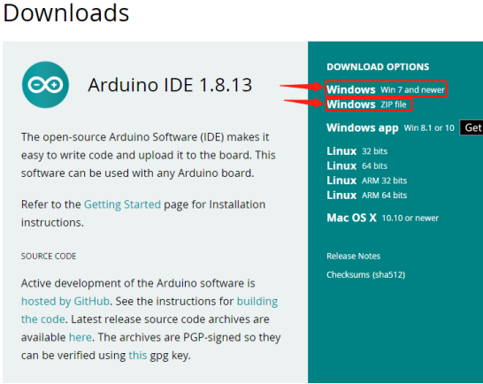
You could download Arduino IDE from the official website:https://www.arduino.cc/, click the SOFTWARE on the browse bar,click“DOWNLOADS” to enter download page, as shown below:

You can download either Windows win7 and newer or Windows ZIP file.
The first one doesn’t require. There are two versions of IDE for WINDOWS system, you can choose from the Installer (.exe) and the Zip packages. We suggest you use the first one that installs directly everything you need to use the Arduino Software (IDE), including the drivers.
With the Zip package you need to install the drivers manually. The Zip file is also useful if you want to create a portable installation.

You just need to click JUST DOWNLOAD.
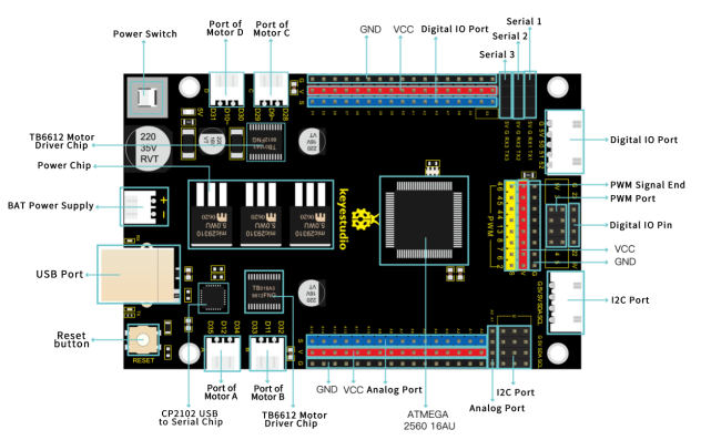
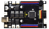
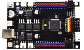
(2).Keyestudio MEGA 2560 Smart Development Board
We need to know keyestudio MEGA 2560 development board, as a core of this smart car.
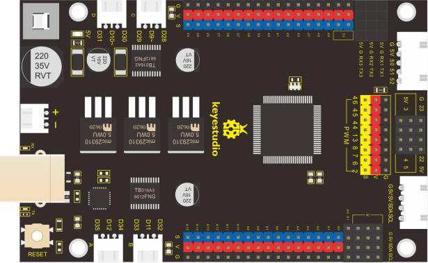
The processor core of MEGA 2560 board is ATMEGA2560-16AU, with the cp2102 chip.
It has 54 digital input/output pins (of which 15 can be used as PWM outputs), 16 analog inputs, 4 UARTs (hardware serial ports), a 16 MHz crystal oscillator, a USB connection, a power jack, 1 ICSP header, and a reset button.
It can be interfaced computer with external power with a USB cable.
Microcontroller |
ATMEGA2560-16AU |
|---|---|
Working Voltage |
5V |
Input Voltage |
DC7-12V |
Digital I/O Pins |
54个 (D0-D53) (pin D9,D10,D11 and D12 control speed of motor |
PWM IO Pins |
15 (D2-D13, D44-D46) |
Analog Input Pins |
16 (A0-A15) |
DC Current per I/O Pin |
20 mA |
DC Current for 3.3V Pin |
50 mA |
Flash Memory |
256 KB (ATMEGA2560-16AU) of which 8 KB used by boot loader |
SRAM |
8 KB (ATMEGA2560-16AU) |
EEPROM |
4 KB (ATMEGA2560-16AU) |
Clock Speed |
16 MHz |
(3).Install Driver on Windows System
Let’s install the driver of keyestudio MEGA 2560 smart development board. The USB-TTL chip on this board adopts CP2102 serial chip. The driver program of this chip is included in Arduino 1.8 version and above, which is convenient. Plugged in USB port, the computer can recognize the hardware and automatically install the driver of CP2102.
If install unsuccessfully, or you intend to install manually, open the device manager of computer. Right click Computer—– Properties—– Device Manager.
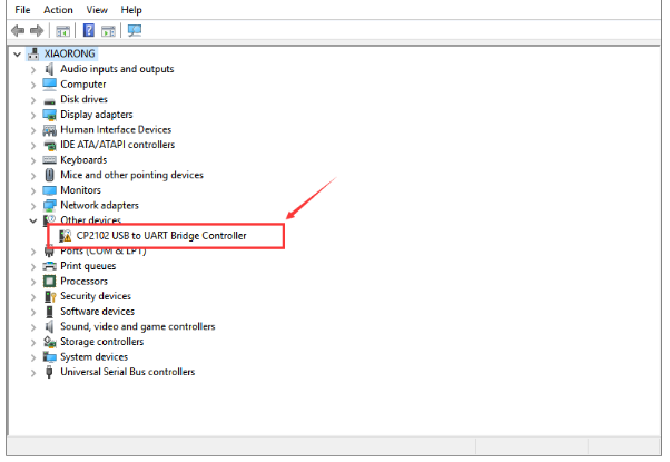
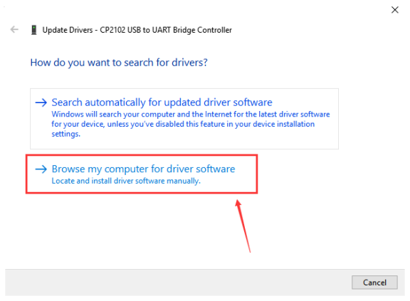
There is a yellow exclamation mark on the page, which implies installing unsuccessfully. Then we double click the hardware and update the driver.
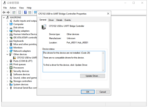
Click“OK”to enter the following page, click“browse my computer for updated driver software”, find out the installed or downloaded ARDUINO software. As shown below:
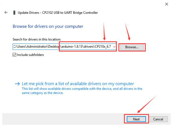
There is a DRIVERS folder in Arduino software installed package. Just open driver folder and you can see the driver of CP210X series chips.
We click“Browse”, then find out the driver folder, or you could enter “driver” to search in rectangular box, then click“next”, the driver will be installed successfully. (I place Arduino software folder on the desktop, you can follow my way)
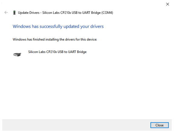
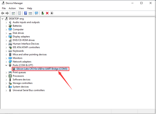
Open device manager, we will find the yellow exclamation mark disappear. The driver of CP2102 is installed successfully.
(4).Install Driver on MAC System
The USB to serial chip of control board is CP2102. We install driver on MAC as follows:
https://wiki.keyestudio.com/How_to_Install_the_Driver_of_CP2102_on_MAC_System
(5).Arduino IDE Setting
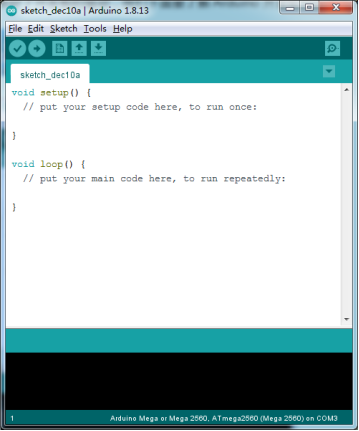
Click icon,open Arduino IDE.
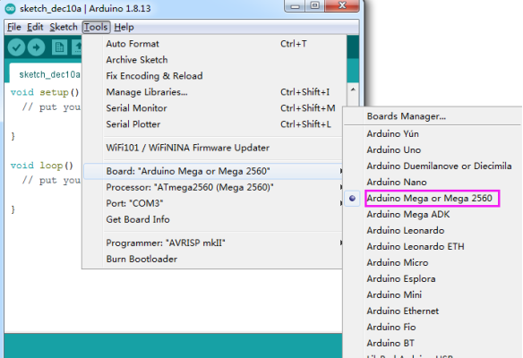
To avoid the errors when uploading the program to the board, you need to select the correct Arduino board that matches the board connected to your computer.
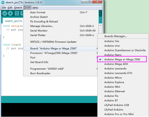
Then come back to the Arduino software, you should click Tools→Board, select the board. (as shown below)
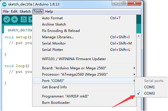
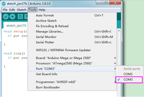
Then select the correct COM port (you can see the corresponding COM port after the driver is successfully installed)

Before uploading the program to the board, let’s demonstrate the function of each symbol in the Arduino IDE toolbar.
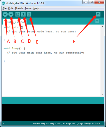
A- Used to verify whether there is any compiling mistakes or not.
B- Used to upload the sketch to your Arduino board.
C- Used to create shortcut window of a new sketch.
D- Used to directly open an example sketch.
E- Used to save the sketch.
F- Used to send the serial data received from board to the serial monitor.
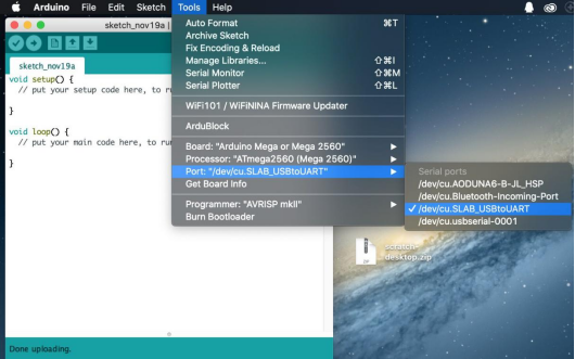
Note: the setting method on Mac system is same as on Windows system except different COM port, as shown below:
(6).Start First Program
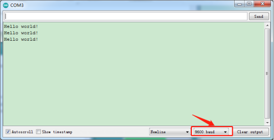
We’ve known how to download and install the driver of development board , next, we will burn a code to show“Hello World!”in the monitor.
Test Code
void setup() {
  // initialize serial communication at 9600 bits per second:
  Serial.begin(9600);
}

void loop() {
  // print out "Hello world!"
  Serial.println("Hello world!");
  delay(1000);// delay 1 second
}
Open Arduino IDE, and set board as follows:
Set COM port, as shown below:
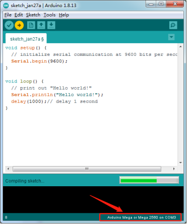
Click to start compiling the program, and check errors.
Click to upload the program, upload successfully.
Upload the program successfully, open serial monitor and set baud rate to 9600, Monitor will print“Hello World!”each 1s.
Congratulation, you finish the first program.
6. Projects
The whole project begins with basic program. Starting from simple to complex, the lessons will guide you to assemble smart motorhome and absorb the knowledge of electronic and machinery step by step. I reckon that you might hardly sit still and itch to have a go, let’s get started.
Note: (G), marked on each sensor and module, is negative pole and connected to“G”,“-”or“GND”on the sensor shield or control board ; (V) is positive pole and interfaced with“V”,“VCC”,“+”or“5V”on the sensor shield or control board.
Project 1: LED Blink
1.Description:
For the starter and enthusiast, this is a fundamental program—LED Blink.
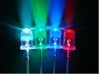
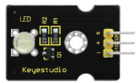
LED, the abbreviation of light emitting diodes, consist of Ga, As, P, N chemical compound and so on. It is often applied to numbers and text display as an indicator in the circuit.
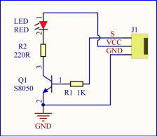
The LED can flash diverse color by altering the delay time in the test code. When in control, power on GND and VCC, the LED will be on if S end is high level; nevertheless, it will go off.
2.Parameter:
Control interface: digital port
Working voltage: DC 3.3-5V
Pin spacing: 2.54mm
LED display color: red
3.Component:
MEGA 2560 Smart Development Board*1 |
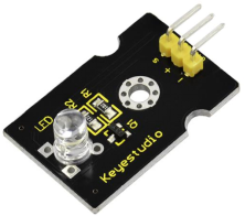
Keyestudio White LED Module*1 |
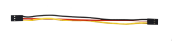
3pin F-F 26AWG Dupont Line |
|---|---|---|
|
|
|
USB Cable*1 |
6-Slot AA Battery Holder |
|
|
|


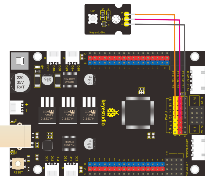
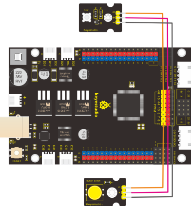
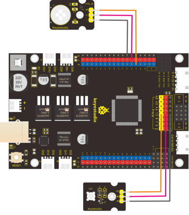
4.Connection Diagram:

From the above diagram, pin -, + and S of LED module are respectively connected to pin G, 5V and D13 of expansion board. Then we compile the code as follows:
5.Test Code:
  /*
  keyestudio smart motorhome
  lesson 1.1
  Blink
  http://www.keyestudio.com
*/
#define LED  13 //define the pin of LED as D13
void setup()
{
  pinMode(LED, OUTPUT);// initialize digital pin LED as an output.
}
void loop() // the loop function runs over and over again forever
{
  digitalWrite(LED, HIGH);   // turn the LED on (HIGH is the voltage level
  delay(1000);    // wait for a second
  digitalWrite(LED, LOW);    // turn the LED off by making the voltage LOW
  delay(1000);    // wait for a second
}
6.Test Result:
Upload the program, LED blinks with the interval of 1s.
7.Code Explanation:
pinMode(LED,OUTPUT) - This function can denote that the pin is INPUT or OUTPUT.
digitalWrite(LED,HIGH) - When pin is OUTPUT, we can set it to HIGH(output 5V) or LOW(output 0V).
8.Extension Practice:
The LED flashes for 1s through the test result, therefore, pins and delay time affect flash frequency.
/*
  keyestudio smart motorhome
  lesson 1.2
  Blink
  http://www.keyestudio.com
*/
#define LED 13 //Define the pin of LED as D13
void setup()
{
  pinMode(LED, OUTPUT);// initialize digital pin LED as an output.
}
void loop() // the loop function runs over and over again forever
{
  digitalWrite(LED, HIGH);   // turn LED on (HIGH is the voltage level
  delay(100);    // wait for a second
  digitalWrite(LED, LOW);    // turn LED off by making the voltage LOW
  delay(100);    // wait for a second
}
The LED flashes faster through the lesson 1.2 test.
Project 2: Adjust LED Brightness
1.Description:
In previous lesson, we control LED on and off and make it blink.
In this project, we will control LED brightness through PWM to simulate breathing effect. Similarly, you can change the step length and delay time in the code so as to demonstrate different breathing effect.
PWM is a means of controlling the analog output via digital means. Digital control is used to generate square waves with different duty cycles (a signal that constantly switches between high and low levels) to control the analog output.
In general, the input voltage of port are 0V and 5V. What if the 3V is required? Or what if switch among 1V, 3V and 3.5V? We can’t change resistor constantly. For this situation, we need to control by PWM.
For the Arduino digital port voltage output, there are only LOW and HIGH, which correspond to the voltage output of 0V and 5V. You can define LOW as 0 and HIGH as 1, and let the Arduino output five hundred 0 or 1 signals within 1 second.
If output five hundred 1, that is 5V; if all of which is 1, that is 0V. If output 010101010101 in this way then the output port is 2.5V, which is like showing movie. The movie we watch are not completely continuous. It actually outputs 25 pictures per second. In this case, the human can’t tell it, neither does PWM. If want different voltage, need to control the ratio of 0 and 1. The more 0,1 signals output per unit time, the more accurately control.
2.Component:
Keyestudio MEGA 2560 Smart Development Board*1 |
Keyestudio White LED Module*1 |
3pin F-F 26AWG Dupont Line |
|---|---|---|
|
|
|
USB Cable*1 |
6-Slot AA Battery Holder |
|
|
|


3.Connection Diagram:
We keep connection diagram unchanged.
4.Test Code:
/*
  keyestudio smart motorhome
  lesson 2.1
  PWM
  http://www.keyestudio.com
*/
#define LED 13 //Define the pin of LED as D13
int value;
void setup()
{
  pinMode(LED, OUTPUT);// initialize digital pin LED as an output.
}
void loop () {
  for (value = 0; value < 255; value = value + 1) {
    analogWrite (LED, value); // LED lights gradually light up
    delay (5); // delay 5MS
  }
  for (value = 255; value > 0; value = value - 1) {
    analogWrite (LED, value); // LED gradually goes out
    delay (5); // delay 5MS
  }
}
5.Test Result:
Upload test code successfully, LED gradually becomes brighter then darker, like human breath.
6.Code Explanation
When we need to repeat some statements, we could use FOR statement.
FOR statement format is shown below:
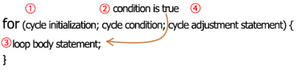
FOR cyclic sequence:
Round 1:1 → 2 → 3 → 4
Round 2:2 → 3 → 4
…
Until number 2 is not established, “for”loop is over,
After knowing this order, go back to code:
for (int value = 0; value < 255; value=value+1){ … }
for (int value = 255; value >0; value=value-1){ … }
The two“for”statements make value increase from 0 to 255, then reduce from 255 to 0, then increase to 255,….infinitely loop
There is a new function in the following —– analogWrite()
We know that digital port only has two state of 0 and 1. So how to send an analog value to a digital value? Here,this function is needed. Let’s observe the Arduino board and find 6 pins marked“~”which can output PWM signals.
Function format as follows:
analogWrite(pin,value)
analogWrite() is used to write an analog value from 0~255 for PWM port, so the value is in the range of 0~255. Attention that you only write the digital pins with PWM function, such as pin 3, 5, 6, 9, 10, 11.
PWM is a technology to obtain analog quantity through digital method. Digital control forms a square wave, and the square wave signal only has two states of turning on and off (that is, high or low levels). By controlling the ratio of the duration of turning on and off, a voltage varying from 0 to 5V can be simulated. The time turning on(academically referred to as high level) is called pulse width, so PWM is also called pulse width modulation.
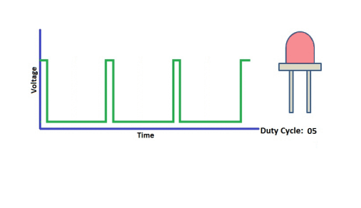
Through the following five square waves, let’s acknowledge more about PWM.
In the above figure, the green line represents a period, and value of analogWrite() corresponds to a percentage which is called Duty Cycle as well. Duty cycle implies that high-level duration is divided by low-level duration in a cycle. From top to bottom, the duty cycle of first square wave is 0% and its corresponding value is 0. The LED brightness is lowest, that is, turn off. The more time high level lasts, the brighter the LED. Therefore, the last duty cycle is 100%, which correspond to 255, LED is brightest. 25% means darker.
PWM mostly is used for adjusting the LED brightness or rotation speed of motor.
It plays vital role in controlling smart robot car. I believe that you can’t wait to enter next project.
7.Extension Practice:
Let’s keep pins unchanged and change the delay value, then observe how LED changes.
/*
  keyestudio smart motorhome
  lesson 2.2
  PWM
  http://www.keyestudio.com
*/
#define LED 13 //Define the pin of LED as D13
int value;
void setup()
{
  pinMode(LED, OUTPUT);// initialize digital pin LED as an output.
}
void loop () {
  for (value = 0; value < 255; value = value + 1) {
    analogWrite (LED, value); // LED lights gradually light up
    delay (20); // delay 30MS
  }
  for (value = 255; value > 0; value = value - 1) {
    analogWrite (LED, value); // LED gradually goes out
    delay (20); // delay 30MS
  }
}
Upload code to development board, the LED’s blink frequency is slower, isn’t it?
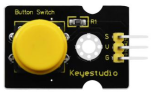
Project 3: Button Module
1.Description:
In this project, we control LED brightness by button module. The low level(0) is output when the button is pressed; however, high level(1) is output when button is released.
2.Specification:
Operating Voltage: 3.3-5V (DC)
Control Signal: Digital signal
Detection Height: 0-3 cm
Weight: 3.8g
Dimension: 34*22*15mm
3.Component:
Keyestudio MEGA 2560 Smart Development Board*1 |
Keyestudio Digital Button Module*1 |
Keyestudio White LED Module*1 |
|---|---|---|
|
|
|
3pin F-F 26AWG Dupont Line *2 |
USB Cable*1 |
6-Slot AA Battery Holder |
|
|
|


4.Connection Diagram:
Note: the pin G, V and S of button sensor are interfaced with pin G, V and D2 of expansion board, and connect pin G, V and S of LED module to G, V and D13 of expansion board.
5.Test Code:
read the signal of button sensor
/*
  keyestudio smart motorhome
  lesson 3.1
  button
  http://www.keyestudio.com
*/
#define button 2 //Define the pin of LED as D12
volatile int buttonState;  //The output level state of button module
void setup()
{
  Serial.begin(9600);//set baud rate to 9600
  pinMode(button, INPUT);// initialize digital pin button as an input.
}
void loop () {
  buttonState = digitalRead(button);
  Serial.println(buttonState);  //auto wrap and output the digital signals from digital 2
  delay(100);//delay in 100ms
}
6.Test Result:
Upload code, open serial monitor to set baud rate to 9600. The number “1”shows up then“0”appears on the monitor.
7.Code Explanation:
Serial.begin(9600)- Initialize serial port, set baud rate to 9600
pinMode(pin, INPUT)-This function can denote that the pin is INPUT or OUTPUT
digitalRead(pin)-Read the state of pin, which are generally HIGH and LOW level. Function digitalRead() will come back to HIGH or LOW level if pins are not connected.
8.Extension Practice:
button-controlled LED
 /*
  keyestudio smart motorhome
  lesson 3.2
  button
  http://www.keyestudio.com
*/
#define LED 13 //Define the pin of LED as D13
#define button 2 //Define the pin of button module as D2
volatile int buttonState;  //the state of button
void setup()
{
  Serial.begin(9600); //set baud rate to 9600
  pinMode(button, INPUT); // initialize digital pin button as an input.
  pinMode(LED, OUTPUT); // initialize digital pin LED as an output.
}
void loop ()
{
  buttonState = digitalRead(button);    //read the status of button
  if (buttonState == 0) //if the button is pressed
  {
    digitalWrite(LED, HIGH);  //Turn on LED
  }
  else
  {
    digitalWrite(LED, LOW);   //turn off LED
  }
  delay(100); //dealy in 100ms
}
It turns out that LED is on when the button is pressed, and LED off when button is released.
Project 4: Line Tracking Sensor
1.Description:
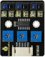
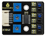
The tracking sensor is actually an infrared sensor. The component used here is the TCRT5000 infrared tube.
Its working principle is to use the different reflectivity of infrared light to the color, then convert the strength of the reflected signal into a current signal.
During the process of detection, black is active at HIGH level, but white is active at LOW level. The detection height is 0-3 cm.
Keyestudio 3-channel line tracking module has integrated 3 sets of TCRT5000 infrared tube on a single board, which is more convenient for wiring and control.
By rotating the adjustable potentiometer on the sensor, it can adjust the detection sensitivity of the sensor.
2.Specification:
Operating Voltage: 3.3-5V (DC)
Interface: 5PIN
Output Signal: Digital signal
Detection Height: 0-3 cm
Note: Adjust the sensitivity by rotating the potentiometer before the test. The sensitivity is best when LED is at on and off state.
3.Component:
MEGA 2560 Smart Development Board*1 |
Line Tracking Sensor*1 |
Keyestudio White LED Module*1 |
|---|---|---|
|
|
|
3pin F-F 26AWG Dupont Line |
5pin XH2.54 to PH2.0 Dupont Line |
USB Cable*1 |
|
|
|
6-Slot AA Battery Holder |
||
|


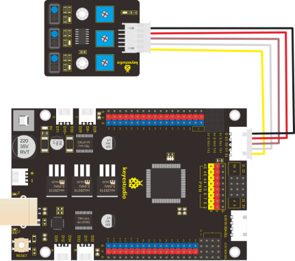
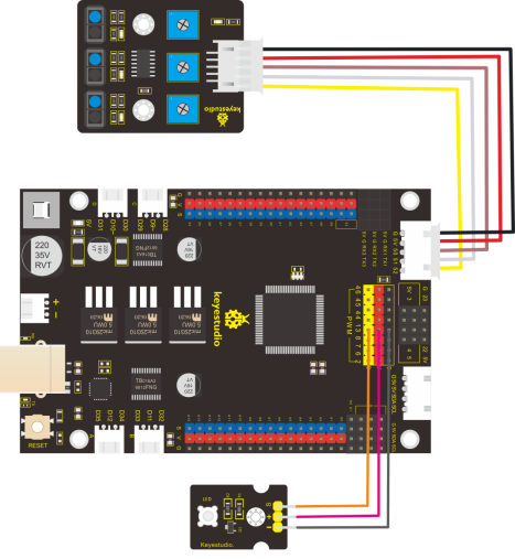
4.Connection Diagram:
5.Test Code:
/*
  keyestudio smart motorhome
  lesson 4.1
  Line Track sensor
  http://www.keyestudio.com
*/
//Line Tracking Sensor
#define L_pin  50
#define M_pin  51
#define R_pin  52
void setup()
{
  Serial.begin(9600); //Set baud rate to 9600
  pinMode(L_pin, INPUT); //set pins of line tracking sensor to INPUT
  pinMode(M_pin, INPUT);
  pinMode(R_pin, INPUT);
}
void loop ()
{
  int L_val = digitalRead(L_pin); //read the value of left sensor
  int M_val = digitalRead(M_pin); //read the value of middle sensor
  int R_val = digitalRead(R_pin); //read the value of right sensor
  Serial.print(L_val);
  Serial.print("  ");
  Serial.print(M_val);
  Serial.print("  ");
  Serial.print(R_val);
  Serial.println("  ");
  delay(100); //delay in 100ms
  }
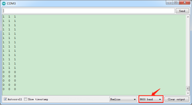
6.Test Result:
Upload code to development board, open serial monitor to check the state of three line tracking sensors. When no signals are received, they are in high level state and“1”shows up ; however, 1 changes into 0 when covering sensor with white paper.
7.Code Explanation:
Serial.begin(9600)-initialize the serial port, set serial baud rate to 9600
pinMode- define the PIN state(input and output) of MCU digitalRead- read the level status of pin(HIGH, LOW)
8.Extension Practice:
We’ve known how line tracking sensor works, next, we connect an LED at pin 13. We will control LED on and off by line tracking sensor, as shown below:
Test Code
/*
  keyestudio smart motorhome
  lesson 4.2
  Line Track sensor
  http://www.keyestudio.com
*/
//LED pin
#define LED 13
//Line Tracking Sensor
#define L_pin  50
#define M_pin  51
#define R_pin  52
void setup()
{
  Serial.begin(9600); //set baud rate to 9600
  pinMode(LED, OUTPUT); //set LED to OUTPUT
  pinMode(L_pin, INPUT); //set the pin of line tracking sensor to INPUT
  pinMode(M_pin, INPUT);
  pinMode(R_pin, INPUT);
}
void loop ()
{
  int L_val = digitalRead(L_pin); //read the value of left sensor
  int M_val = digitalRead(M_pin); //read the value of middle sensor
  int R_val = digitalRead(R_pin); //read the value of right sensor
  Serial.print(L_val);
  Serial.print("  ");
  Serial.print(M_val);
  Serial.print("  ");
  Serial.print(R_val);
  Serial.println("  ");
  delay(100); //delay in 100ms
  if (L_val == 0 || M_val == 0 || R_val == 0) {
    digitalWrite(LED, HIGH);
  }
  else {
    digitalWrite(LED, LOW);
  }
}
Upload the code to development board, we observe LED get brighter when covering the line tracking sensor by hand.
Project 5: PIR Motion Sensor
1.Description:
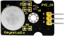
The Pyroelectric infrared motion sensor can detect infrared signals from a moving person or animal, and output switching signals. It can be applied to a variety of occasions to detect the movement of human body. Conventional pyroelectric infrared sensors are much more bigger, with complex circuit and lower reliability. Now we launch this new pyroelectric infrared motion sensor, specially designed for ARDUINO. This sensor integrates a digital pyroelectric infrared sensor and connecting pins. It features higher sensibility and reliability, lower power consumption, light weight, small size, lower voltage working mode and simpler peripheral circuit.
2.Specification:
Input voltage: DC 3.3V ~ 5V
Working current: 15uA
Working temperature: -20 ~ 85 degrees Celsius
Output voltage: high 3 V, low 0 V
Output delay time (high level): about 2.3 to 3 seconds
Detection angle: about 100 °
Detection distance: 3-4 meters
Output indicator LED (high-level )
Pin limit current: 100mA
Note:
1. The maximum distance is 3-4 meters during testing.
2. When testing, firstly open the white lens, you can see the rectangular sensing part. When the long line of the rectangular sensing part is parallel to the ground, the distance is the best.
3. When testing, need to cover the sensor with white lens, otherwise it will affect the distance.
4. The distance is best at 25℃, and the detection distance is shortened when it exceeds 30℃.
5. Done powering up and uploading the code, you need to wait 5-10 seconds then start testing, otherwise it is not sensitive.
3.Component:
MEGA 2560 Smart Development Board*1 |
Keyestudio PIR Motion Sensor*1 |
Keyestudio White LED Module*1 |
|---|---|---|
|
|
|
3pin F-F 26AWG Dupont Line*2 |
USB Cable*1 |
6-Slot AA Battery Holder |
|
|
|


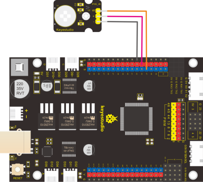
4.Connection Diagram
Note: on expansion board, the pin G, V and S of PIR motion sensor are connected to G, V and 47; pin G, V and S of LED module are connected to G, V and 13.
5.Test Code:
/*
  keyestudio smart motorhome
  lesson 5.1
  PIR
  http://www.keyestudio.com
*/

//PIR Motion Sensor
#define PIR  47   //PIR pin to D47

void setup()
{
  Serial.begin(9600); //set baud rate to 9600
  pinMode(PIR, INPUT); //set the pin of PIR motion sensor to INPUT
}

void loop ()
{
  int val = digitalRead(PIR); //set the variable val to the value read
  Serial.println(val);
  delay(100); //delay in 100ms
}
6.Test Result:
Upload code, open serial monitor and set baud rate to 9600. The serial monitor will show“1”when PIR motion sensor detects people around; on the contrary, number“0”will appear on the monitor when nobody is detected.

7.Project Extension:
/*
  keyestudio smart motorhome
  lesson 5.2
  PIR
  http://www.keyestudio.com
*/

//PIR Motion Sensor
#define PIR  47   //PIR pin to D47
#define LED  13   //LED pin to D13
void setup()
{
  pinMode(LED, OUTPUT); //set LED to OUTPUT
  pinMode(PIR, INPUT); //set PIR motion sensor to INPUT

}
void loop ()
{
  int val = digitalRead(PIR); //set val to the value read by sensor
  if (val == 1) {   //People is detected
    digitalWrite(LED, HIGH); //turn on LED
  }
  else {
    digitalWrite(LED, LOW); //otherwise, lED will be off
  }

}
The LED connected to digital 13 will be on when the sensor detects people moving, otherwise, LED will be off.
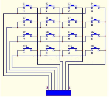
Project 6: 4*4 Membrane Keypad
1.Description:
To save I/O ports of MCU, we make a Membrane Keypad. In this project, we will nmake an experiment; serial monitor will display the corresponding character when the membrane keypad is pressed.
Schematic Diagram:
2.Specification:
Working Voltage: 3.3V~5V
Port: digital port
3.Component:
Keyestudio MEGA 2560 Smart Development Board*1 |
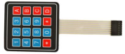
Keyestudio 4*4Membrane Keypad*1 |
8pin M-F 26AWG Dupont Line *1 |
|---|---|---|
|
|
|
USB Cable*1 |
6-Slot AA Battery Holder |
|
|
|


4.Connection Diagram:
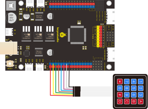
5.Test Code:
/*
  keyestudio smart motorhome
  lesson 6.1
  Keypad
  http://www.keyestudio.com
*/

#include <Keypad.h>
const byte ROWS = 4; //four rows
const byte COLS = 4; //four columns
char keypressed;
//define the cymbols on the buttons of the keypads
char keyMap[ROWS][COLS] = {
  {'1', '2', '3', 'A'},
  {'4', '5', '6', 'B'},
  {'7', '8', '9', 'C'},
  {'*', '0', '#', 'D'}
};
byte rowPins[ROWS] = {14, 15, 16, 17}; //Row pinouts of the keypad
byte colPins[COLS] = {36, 37, 38, 39}; //Column pinouts of the keypad
Keypad myKeypad = Keypad( makeKeymap(keyMap), rowPins, colPins, ROWS, COLS);

void setup()
{
  Serial.begin(9600); //set baud rate to 9600

}
void loop ()
{
  keypressed = myKeypad.getKey(); //read key value
  if (keypressed != NO_KEY) { //read key value
    Serial.print("key:");
    Serial.println(keypressed); //print key value
  }

}
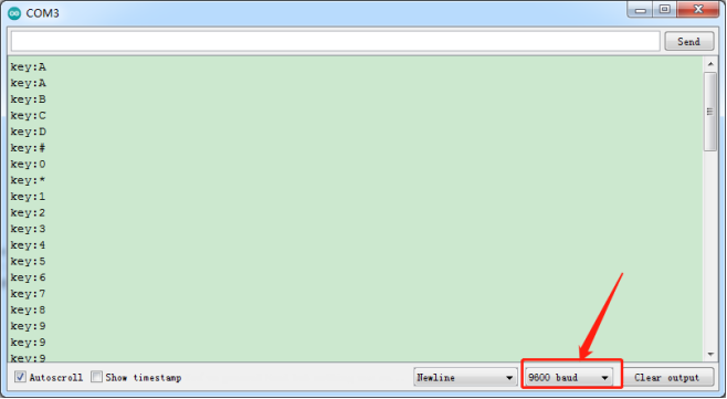
6.Test Result:
Download code, open serial monitor and set baud rate to 9600. The serial monitor will show the corresponding key value when the key of membrane keypad is pressed, as shown below;
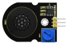
Project 7: Power Amplifier Module
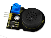
1.Description:
We can use Arduino to make many interactive works of which the most commonly used is acoustic-optic display.
All the previous experiment has something to do with LED. However, the experiment of this chapter is related to produce sound. Normally, the experiment is done with a buzzer or a speaker.
In this lesson, we will replace buzzer with power amplifier module, input different frequencies square wave to emit different sound like“do re mi fa so la si do”.
2.Specification:
Control interface: digital port
Working voltage: DC 3.3-5V
3.Component:
Keyestudio MEGA 2560 Smart Development Board*1 |
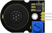
Keyestudio Power Amplifier Module*1 |
3pin F-F 26AWG Dupont Line |
|---|---|---|
|
|
|
USB Cable*1 |
6-Slot AA Battery Holder |
|
|
|


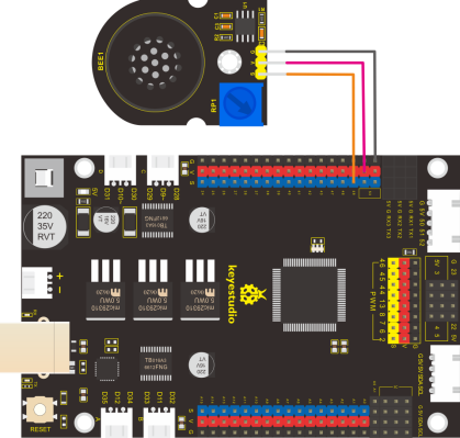
4.Connection Diagram:
Note: the pin G, V and S of passive buzzer are connected to pin G, V and D49 of expansion board
5.Test Code:
/*
  keyestudio smart car
  lesson 7.1
  buzzer
  http://www.keyestudio.com
*/

#define buzzer 49 //buzzer pin to D49

void setup() {
  pinMode(buzzer, OUTPUT);//set digital 49 to OUTPUT
}

void loop () {
  tone(buzzer, 262);  //buzzer emits the sound with 262Hz
  delay(250);   //delay in 250ms
  tone(buzzer, 294);;   //buzzer emits the sound with 294Hz
  delay(250);   //delay in 250ms
  tone(buzzer, 330);
  delay(250);
  tone(buzzer, 349);
  delay(250);
  tone(buzzer, 392);
  delay(250);
  tone(buzzer, 440);
  delay(250);
  tone(buzzer, 494);
  delay(250);
  tone(buzzer, 532);
  delay(250);
  noTone(buzzer);   //buzzer turns off sound output
  delay(1000);
}
6.Test Result:
Upload code to MEGA 2560 smart development board, power amplifier module will emit“do re mi fa so la si do”.
7.Project Extension:
Playing Music
/*
  keyestudio smart car
  lesson 7.1
  buzzer
  http://www.keyestudio.com
*/

#define buzzer 49 //buzzer pin to D49

void setup() {
  pinMode(buzzer, OUTPUT);//set digital 49 to OUTPUT
}

void loop () {
  tone(buzzer, 262);  //buzzer emits the sound with 262Hz
  delay(250);   //delay in 250ms
  tone(buzzer, 294);;   //buzzer emits the sound with 294Hz
  delay(250);   //delay in 250ms
  tone(buzzer, 330);
  delay(250);
  tone(buzzer, 349);
  delay(250);
  tone(buzzer, 392);
  delay(250);
  tone(buzzer, 440);
  delay(250);
  tone(buzzer, 494);
  delay(250);
  tone(buzzer, 532);
  delay(250);
  noTone(buzzer);   //buzzer turns off sound output
  delay(1000);
}
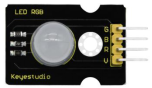
Project 8: RGB Module
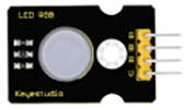
1.Description:
In the previous project, we know how to control the LED brightness.Yet, in this chapter, we will learn a special LED—- RGB. RGB LED is divided into
Common cathode means that all the cathodes are connected to a single pin. Common anode means that all the anodes are connected to a single pin. We use common anode RGB.
Common anode RGB LED has 4 pins and its anodes are interfaced with +5V. The rest of LEDs need a 220Ω resistor in cascade series to prevent circuit from burning.
We need to interface R, G and B signal ends of RGB with PWM ports of MCU. In addition, the color proportion of LED can be controlled by adjusting three PWM values, that is, LED can display different colors.
The larger corresponding color proportion is, the larger the PWM value we set.
2.Specification:
Working voltage: DC 5V
Working current: 0.6A (maximum)
Maximum power: 0.3W
Working temperature: -25~+65℃
Interface: 4pin header (spacing 2.54mm)
Positioning hole: 3mm in diameter
Size: 30*20mm
Environmental protection attributes: ROHS
3.Component:
Keyestudio MEGA 2560 Smart Development Board*1 |
Keyestudio 10mm Highlight Full-color LED Module*2 |
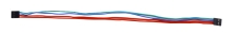
4pin F-F 26AWG Dupont Line *2 |
|---|---|---|
|
|
|
USB Cable*1 |
6-Slot AA Battery Holder |
|
|
|


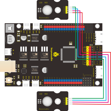
4.Connection Diagram:
5.Test Code:
/*
  keyestudio smart motorhome
  lesson 8.1
  RGB
  http://www.keyestudio.com
*/

#define RGB_R  3  //define pin R of RGB as D3
#define RGB_B  4  // define pin B of RGB as D4
#define RGB_G  5  //define pin B of RGB as D5

void setup() {
  pinMode(RGB_R, OUTPUT); //set the digital ports to OUTPUT
  pinMode(RGB_G, OUTPUT);
  pinMode(RGB_B, OUTPUT);
}

void loop () {
  set_RGBColor(0,255,255);   //red
  delay(500);
  set_RGBColor(255,0,255);   //green
  delay(500);
  set_RGBColor(255,255,0);   //blue
  delay(500);
}

//set color
void set_RGBColor(int red, int green, int blue) {
  analogWrite(RGB_R, red);
  analogWrite(RGB_G, green);
  analogWrite(RGB_B, blue);
}
6.Test Result:
After uploading code, RGB module shows red, green and blue colors.
7.Project Extension:
display random color
/*
  keyestudio smart motorhome
  lesson 8.2
  RGB
  http://www.keyestudio.com
*/

#define RGB_R  3  //define the pin R of RGB as D3
#define RGB_B  4  //set pin B of RGB to D4
#define RGB_G  5  //set pin g of RGB to D5
int r, g, b;
void setup() {
  pinMode(RGB_R, OUTPUT); // set digital ports of RGB to OUTPUT
  pinMode(RGB_G, OUTPUT);
  pinMode(RGB_B, OUTPUT);
}

void loop () {
  //choose a random number from 0 to 255
  r = random(255);
  g = random(255);
  b = random(255);
  set_RGBColor(r, g, b); //random colors
  delay(500);
}

//set color
void set_RGBColor(int red, int green, int blue) {
  analogWrite(RGB_R, red);
  analogWrite(RGB_G, green);
  analogWrite(RGB_B, blue);
}
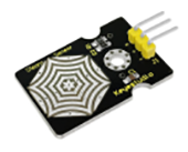
Project 9: Adjustable Rotary Potentiometer
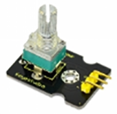
1.Description:
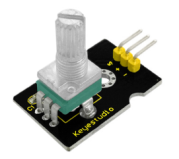
There is a rotary potentiometer module which uses a 10K adjustable resistor in this kit. By rotating the potentiometer, we can change the value of the resistor and then build the circuit to convert the resistance change into the voltage change. In addition, its voltage can be divided into 1025 parts and can be easily connected to 2560 control board.
In this chapter, we will adjust LED brightness by potentiometer.
2.Specification:
Operating voltage: 3.3V to 5V
Interface: analog interface
3.Component:
Keyestudio MEGA 2560 Smart Development Board*1 |
Keyestudio Adjustable Rotary Potentiometer*1 |
Keyestudio White LED Module*1 |
|---|---|---|
|
|
|
3pin F-F 26AWG Dupont Line*2 |
USB Cable*1 |
6-Slot AA Battery Holder |
|
|
|


4.Connection Diagram:
5.Test Code:
/*
  keyestudio smart motorhome
  lesson 9.1
  Adjustable potentiometer
  http://www.keyestudio.com
*/
#define RES  A3   //potentiometer pin to A3
volatile int value=0;
void setup() {
  Serial.begin(9600);//set baud rate
}

void loop () {
  value = analogRead(RES);  //read the value of potentiometer
  Serial.println(value);    //print value
  delay(100);               //delay in 100MS
}
6.Code Explanation:
In the project,we set pins to A3.
Set a integer to variable value and assign the detected result to value.
Serial monitor shows the value of variable value, and set baud rate to 9600.
analogRead(pin)-read the analog value of pin, mega2560 control board had 16 analog ports (A0-A15), in the range of 0~1023,that is, the accuracy is 5V/1024=0.0049V.
map(value, fromLow, fromHigh, toLow, toHigh)-value is mapped value, fromLow- current value range lower limit,fromHigh- current value range upper limit,toLow- target value range lower limit, toHigh-target value range upper limit.
7.Test Result:
Upload code, power on with USB cable, open serial monitor and set baud rate to 9600. The serial monitor shows the corresponding analog value.
In the project, rotate the potentiometer clockwise, and the analog value increases; yet, the analog value(0-1023) decreases if rotating anticlockwise, as shown below:
8.Project Extension:
Control LED brightness by potentiometer
/*
  keyestudio smart motorhome
  lesson 9.2
  Adjustable potentiometer
  http://www.keyestudio.com
*/
#define RES A3   //set potentiometer pin to A3
#define LED 13   //define the pin of LED as D13
volatile int value = 0;
void setup() {
  pinMode(LED, OUTPUT);// initialize digital pin LED as an output.
}

void loop () {
  value = analogRead(RES);  //read the value of potentiometer
  int light = map(value, 0, 1023, 0, 255); //map the analog value 0~1023 of potentiometer to 0~255
  analogWrite(LED, light);   //set LED brightness to light
  delay(100);               //delay in 100MS
}
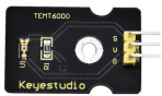
Project 10: Ambient Light Sensor
1.Description:
Ambient light sensor adopts TEMT6000 element which is a high sensitivity and visible photo sensitive (NPN type) triode. It can catch tiny light ray, amplify for 100 times and be recognized by MCU. What’s more, the reaction to light is similar to human eyes, which can determine light intensity and help create interactive appliances.
2.Specification:
Working voltage: 3.3V-5V (DC)
Interface: 3PIN interface
Output signal: analog signal
Weight: 2.3g
3.Component:
Keyestudio MEGA 2560 Smart Development Board*1 |
Keyestudio Ambient Light Sensor*1 |
Keyestudio White LED Module*1 |
|---|---|---|
|
|
|
3pin F-F 26AWG Dupont Line*2 |
USB Cable*1 |
6-Slot AA Battery Holder |
|
|
|


4.Connection Diagram:
Note: pin G,V and S of ambient light sensor are separately interfaced with G, V and A4; pin G, V and S of LED module are connected to G, V and 13.
5.Test Code:
/*
keyestudio smart motorhome
lesson 10.1
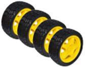
photovaristor
http://www.keyestudio.com
*/
#define photos A4 //set photoresistance pin to A4
#define LED 13 //define the pin of LED as D13
volatile int value = 0;
void setup() {
Serial.begin(9600);
pinMode(LED, OUTPUT);// initialize digital pin LED as an output.
}
void loop () {
value = analogRead(photos); //read the value of photoresistor
Serial.println(value);
if (value < 300) { //when the analog vlaue is les than 300
digitalWrite(LED, HIGH); //turn on LED
}
else { //when the analog value is higher than 300
digitalWrite(LED, LOW); //turn off LED
}
delay(100); //delay in 100MS
}
6.Test Result:
Wire up, upload code and set baud rate to 9600. We see the value detected by ambient light sensor.
The value reduces when covering ambient sensor, however, LED will be on when the value is less than 300; on the contrary, LED will be off.
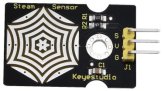
Project 11:Steam Sensor
1.Description:
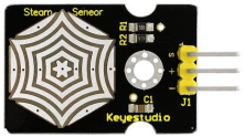
This is a commonly used steam sensor. Its principle is to detect the amount of water by bare printed parallel lines on the circuit board. The more the water is, the more wires will be connected. As the conductive contact area increases, the output voltage will gradually rise. It can detect water vapor in the air as well. The steam sensor can be used as a rain water detector and level switch. When the humidity on the sensor surface surges, the output voltage will increase.
The sensor is compatible with various microcontroller control boards, such as Arduino series microcontrollers. When using it, we provide the guide to operate steam sensor and Arduino control board. Connect the signal end of the sensor to the analog port of the microcontroller, sense the change of the analog value, and display the corresponding analog value on the serial monitor.
Note: the connect part is not waterproof, don’t immerse it in the water please.
2.Specification:
Working voltage: DC 3.3-5V
Working current: <20mA
Operating temperature range: -10℃~+70℃;
Control signal: analog signal output
Interface: 2.54mm 3pin pin interface
Size: 35*20*8mm
Weight: 2.2g
Pin Description:
S:signal pin output
V(+):Power(VCC)
G(-):Ground(GND)
3.Component:
MEGA 2560 Smart Development Board*1 |
Keyestudio Steam Sensor *1 |
Keyestudio Power Amplifier Module*1 |
|---|---|---|
|
|
|
3pin F-F 26AWG Dupont Line*2 |
USB Cable*1 |
6-Slot AA Battery Holder |
|
|
|


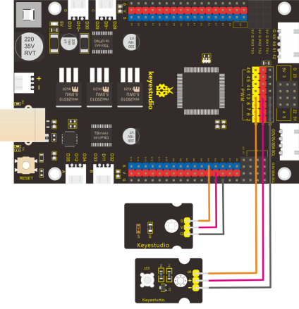
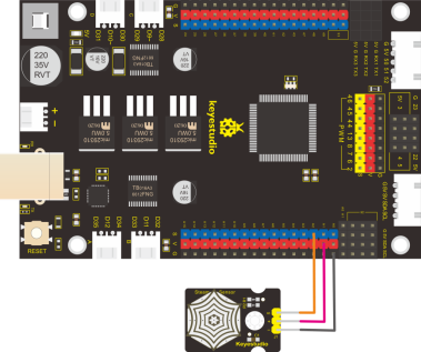
4.Connection Diagram:
Note: on expansion board, pin G, V and S of steam sensor are connected to G, V and A2.
5.Test Code:
/*
  keyestudio smart motorhome
  lesson 11.1
  water sensor
  http://www.keyestudio.com
*/
#define waterpin A5 //water sensor pin to A5
volatile int water = 0;

void setup() {
  Serial.begin(9600);

}

void loop () {
  water = analogRead(waterpin);  //read the analog value of water sensor
  Serial.println(water);
  delay(100);
}
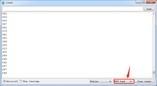
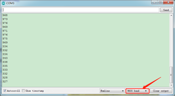
6.Test Result:
Upload code, power on according to connection diagram, open serial monitor and set baud rate to 9600. The value on monitor increases when the water is on steam sensor; whereas, the value decreases when the water is wiped off.
7.Project Extension:
Power amplifier module will alarm when the water content exceeds 300
/*
  keyestudio smart motorhome
  lesson 11.2
  water sensor
  http://www.keyestudio.com
*/
#define waterpin A5 //define the pin of water sensor as A5
#define buzzer   49 //define the pin of buzzer as D49
volatile int water = 0;
void setup() {
  Serial.begin(9600);
  pinMode(buzzer, OUTPUT);//set buzzer to OUTPUT
}

void loop () {
  water = analogRead(waterpin);  //read the analog value of water sensor
  Serial.println(water);
  if (water > 300) {  //when the analog value is more than 300
    tone(buzzer,2000); //buzzer emits the sound with 2000Hz
  }
  else {  //when the analog value is less than 300
    noTone(buzzer); //turn off buzzer
  }
}
Project 12 Analog Gas(MQ-2)Sensor
1.Description:
This gas sensor is used for household gas leak alarms, industrial combustible gas alarms and portable gas detection instruments. And it is suitable for the detection of liquefied gas, benzene, alkane, alcohol, hydrogen, etc., and widely used in various fire alarm systems. The MQ-2 smoke sensor can be accurately a multi-gas detector, and has the advantages of high sensitivity, fast response, good stability, long life, and simple drive circuit.
It can detect the concentration of flammable gas and smoke in the range of 300~10000ppm.Meanwhile, it has high sensitivity to natural gas, liquefied petroleum gas and other smoke, especially to alkanes smoke.
It must be heated for a period of time before using the smoke sensor, otherwise the output resistance and voltage are not accurate. However, the heating voltage should not be too high, otherwise it will cause my internal signal line to blow.
It is belongs to the tin dioxide semiconductor gas-sensitive material, and belongs to the surface ion type N-type semiconductor. At a certain temperature, tin dioxide adsorbs oxygen in the air and forms negative ion adsorption of oxygen, reducing the electron density in the semiconductor, thereby increasing its resistance value. When in contact with flammable gas in the air and smog, if the potential barrier at the grain boundary is adjusted by the smog, it will cause the surface conductivity to change. With this, information about the presence of smoke or flammable gas can be obtained. The greater the concentration of smoke or flammable gas in the air, the greater the conductivity, and the lower the output resistance, the larger the analog signal output. The sensor comes with a positioning hole, which is convenient for you to fix the sensor to other devices. In addition, the sensitivity can be adjusted by rotating the potentiometer.
2.Specification:
Working voltage: 3.3-5V (DC)
Interface: 4 pins (GND, VCC, D0, A0)
Output signal: digital signal and analog signal
Weight: 7.5g
3.Component:
Keyestudio MEGA 2560 Smart Development Board*1 |
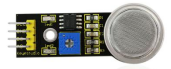
Keyestudio Analog Gas Sensor *1 |
Keyestudio Power Amplifier Module*1 |
|---|---|---|
|
|
|
3pin F-F 26AWG Dupont Line*2 |
4pin F-F 26AWG Dupont Line *1 |
USB Cable*1 |
|
|
|
6-Slot AA Battery Holder |
||
|


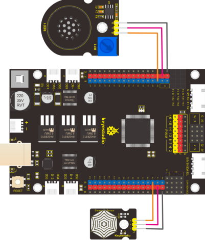
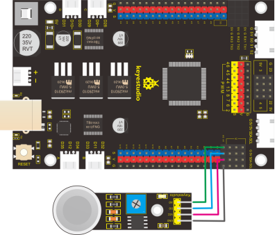
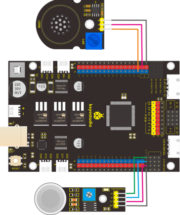
4.Connection Diagram:
Note: on expansion board, the pin GND, VCC, D0 and A0 of analog gas(MQ-2)sensor are interfaced with G,V, A1 and A0.
5.Test Code:
/*
  keyestudio smart motorhome
  lesson 12.1
  MQ2
  http://www.keyestudio.com
*/
#define MQ2_A   A0  //define the pin mq2 as A0
#define MQ2_D   A1  //define the pin mq2 as A1
volatile int analogVal,digitalVal;

void setup() {
  Serial.begin(9600);

}

void loop () {
  digitalVal = digitalRead(MQ2_D);  //read the digital value
  analogVal = analogRead(MQ2_A);  //read the analog value
  Serial.print("digitalVal:");
  Serial.print(digitalVal);
  Serial.print("  analogVal:");
  Serial.println(analogVal);
  delay(100);
}
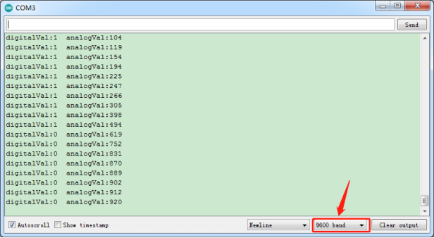
6.Test Result:
Wire up, upload code and open serial monitor to set baud rate to 9600.
The analog value increases and digital level varies from 1 to 0 when the combustible gas is detected.
7.Project Extension:
Power amplifier module will alarm when the detected combustible gas is leaked.
/*
  keyestudio smart motorhome
  lesson 12.2
  MQ2
  http://www.keyestudio.com
*/
#define MQ2_A   A0  // define MQ2_A as A0
#define MQ2_D   A1  //define MQ2_A as A1
#define buzzer  49 //buzzer pin to D49
volatile int analogVal, digitalVal;

void setup() {
  Serial.begin(9600);

}

void loop () {
  analogVal = analogRead(MQ2_A);  //read the analog value
  Serial.println(analogVal);      //print the value of sensor
  if (analogVal > 150) {          //when analog value exceeds 150, the buzzer will alarm
    tone(buzzer, 1000);
  }
  else {
    noTone(buzzer); //turn off buzzer
  }
  delay(100);

}
Project 13 DHT11 Temperature and Humidity Sensor
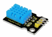
1.Description:
This DHT11 Temperature and Humidity Sensor is a composite sensor which contains a calibrated digital signal output of the temperature and humidity. Its technology ensures high reliability and excellent long-term stability. A high-performance 8-bit microcontroller is connected.
This sensor includes a resistive element and a sense of wet NTC temperature measuring devices. It has excellent quality, fast response, anti-interference ability and high cost performance advantages. Each DHT11 sensor features extremely accurate calibration data of humidity calibration chamber. The calibration coefficients stored in the OTP program memory, internal sensors detect signals in the process, and we should call these calibration coefficients. The single-wire serial interface system is integrated to make it quick and easy. Qualities of small size, low power, and 20-meter signal transmission distance make it a wide applied application or even the most demanding one.
2.Specification:
Supply Voltage: +5 V
Temperature range: 0-50 ℃ error of ± 2 ℃
Humidity: 20-90% RH ± 5% RH error
Interface: Digital
3.Component:
Keyestudio MEGA 2560 Smart Development Board*1 |
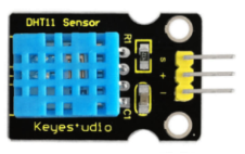
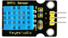
Keyestudio DHT11 Temperature and Humidity Sensor*1 |
3pin F-F 26AWG Dupont Line |
|---|---|---|
|
|
|
USB Cable*1 |
6-Slot AA Battery Holder |
|
|
|


4.Connection Diagram:
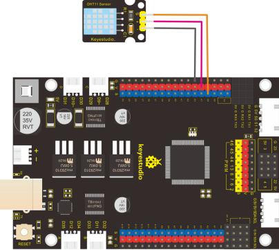
In the project, we need to import the library of DHT11.
5.Test Code:
/*
  keyestudio smart motorhome
  lesson 13.1
  DHT11
  http://www.keyestudio.com
*/
#include <dht11.h>  //include the library code:
dht11 DHT;
#define DHT11_PIN 47 //define DHT11 as 48

void setup() {
  Serial.begin(9600);

}

void loop () {
  int chk;
  chk = DHT.read(DHT11_PIN);    // READ DATA
  switch (chk) {
    case DHTLIB_OK:
      break;
    case DHTLIB_ERROR_CHECKSUM:
      break;
    case DHTLIB_ERROR_TIMEOUT:
      break;
    default:
      break;
  }
  // DISPLAT DATA
  Serial.print("humidity:");
  Serial.print(DHT.humidity);
  Serial.print("   temperature:");
  Serial.println(DHT.temperature);
  delay(100);
}
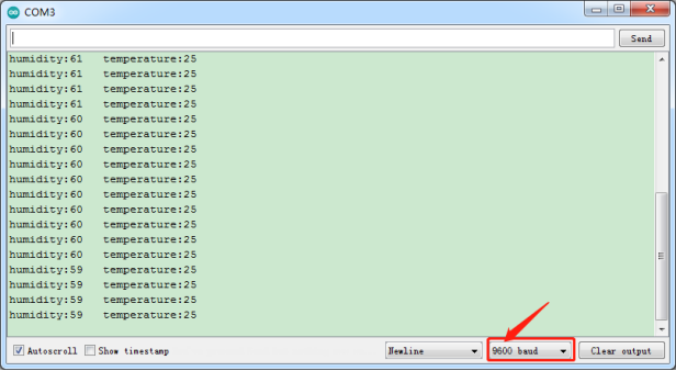
6.Test Result:
Upload code, power on with USB cable,open serial monitor and the temperature and humidity data is shown below:
Project 14 Servo Control
1.Description:
Servo motor is a position control rotary actuator. It mainly consists of housing, circuit board, core-less motor, gear and position sensor. Its working principle is that the servo receives the signal sent by MCU or receiver and produces a reference signal with a period of 20ms and width of 1.5ms, then compares the acquired DC bias voltage to the voltage of the potentiometer and obtain the voltage difference output.
When the motor speed is constant, the potentiometer is driven to rotate through the cascade reduction gear, which leads that the voltage difference is 0, and the motor stops rotating. Generally, the angle range of servo rotation is 0° –180 °
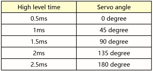
The rotation angle of servo motor is controlled by regulating the duty cycle of PWM (Pulse-Width Modulation) signal. The standard cycle of PWM signal is 20ms (50Hz). Theoretically, the width is distributed between 1ms-2ms, but in fact, it’s between 0.5ms-2.5ms. The width corresponds the rotation angle from 0° to 180°. But note that for different brand motor, the same signal may have different rotation angle.
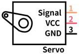
In general, servo has three line in brown, red and orange. Brown wire is grounded, red one is positive pole line and orange one is signal line.
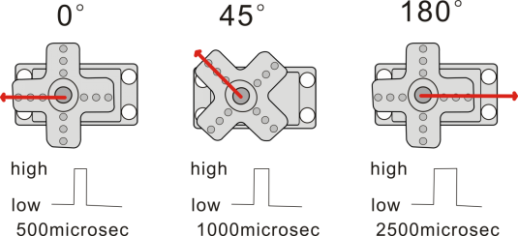
The corresponding servo angles are shown below:
2.Specification:
Working voltage: DC 4.8V ~ 6V
Operating angle range: about 180 ° (at 500 → 2500 μsec)
Pulse width range: 500 → 2500 μsec
No-load speed: 0.12 ± 0.01 sec / 60 (DC 4.8V) 0.1 ± 0.01 sec / 60 (DC 6V)
No-load current: 200 ± 20mA (DC 4.8V) 220 ± 20mA (DC 6V)
Stopping torque: 1.3 ± 0.01kg · cm (DC 4.8V) 1.5 ± 0.1kg · cm (DC 6V)
Stop current: ≦ 850mA (DC 4.8V) ≦ 1000mA (DC 6V)
Standby current: 3 ± 1mA (DC 4.8V) 4 ± 1mA (DC 6V)
3.Component:
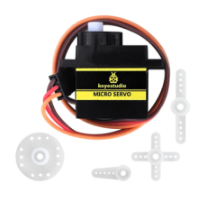
MEGA 2560 Smart Development Board*1 |
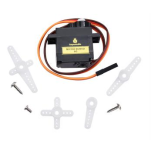
Keyestudio 180° Servo*1 |
|---|---|
|
|
6-Slot AA Battery Holder |
USB Cable*1 |
|
|


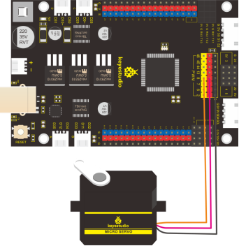
4.Connection Diagram:
Note: The servo is connected to G (GND), V (VCC),8. The brown wire of the servo is connected to Gnd (G), the red wire is linked with 5v (V), and the orange wire is connected to digital pin 8.
Remember to connect external power due to the high current of driving motor.
5.Test Code1:
/*
  keyestudio smart motorhome
  lesson 14.1
  servo
  http://www.keyestudio.com
*/
int servoPin = 8; //pin of servo

void setup() {
  pinMode(servoPin, OUTPUT);//set the pin of servo to OUTPUT
}
void loop() {
  servopulse(servoPin, 0);//rotate to 0°
  delay(1000);//delay 1s
  servopulse(servoPin, 90);//rotate to 900°
  delay(1000);
  servopulse(servoPin, 180);//rotate to 180°
  delay(1000);
}

void servopulse(int pin, int myangle) { //output function
  int pulsewidth = map(myangle, 0, 180, 500, 2500); //map angle to pulsewidth
  for (int i = 0; i < 10; i++) { //output pulse
    digitalWrite(pin, HIGH);//set level of servo port to HIGH
    delayMicroseconds(pulsewidth);//delay the time of pulsewidth
    digitalWrite(pin, LOW);//set the level of servo port to LOW
    delay(20 - pulsewidth / 1000);
  }
}
6.Test Result:
Upload code successfully, servo swings forth and back in the range of 0° 90° and 180°.
There is another guide for restraining servo—- servo library file, the following link of official website is for your reference.
https://www.arduino.cc/en/Reference/Servo
7.Test Code2:
servo swings in the range of 0° to 180°.
/*
  keyestudio smart motorhome
  lesson 14.2
  servo
  http://www.keyestudio.com
*/
#include <Servo.h>  //include the library code:
Servo myservo;

void setup() {
  myservo.attach(8);  //connect servo to digital 8

}

void loop () {
  //rotate 0° to 180°
  for (int i = 0; i < 180; i++) {
    myservo.write(i);
    delay(20);
  }
  delay(1000);  //delay in 1s

  //rotate from 180° to 0°
  for (int i = 180; i > 0; i--) {
    myservo.write(i);
    delay(20);
  }
  delay(1000);  //delay in 1s
}
8.Code Explanation:
Arduino comes with #include <Servo.h> (servo function and statement)
The following are some common statements of the servo function:
1. attach(interface)——Set the pin of servo.
2. write(angle)——The statement to set rotation angle of servo, the angle range is from 0° to 180°.
3. read()——The statement to read angle of servo, read the command value of“write()”.
4. attached()——Judge if the parameter of servo is sent to its interface
Note: The above written format is“servo variable name, specific statement()”, for instance: myservo.attach(8)
Project 15 Ultrasonic Sensor
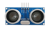
1.Description:
The HC-SR04 ultrasonic sensor uses sonar to determine distance to an object like bats do. It offers excellent non-contact range detection with high accuracy and stable readings in an easy-to-use package. It comes complete with ultrasonic transmitter and receiver modules.The HC-SR04 or the ultrasonic sensor is being used in a wide range of electronics projects for creating obstacle detection and distance measuring application as well as various other applications. Here we have brought the simple method to measure the distance with Arduino and ultrasonic sensor and how to use ultrasonic sensor with Arduino.
2.Specification:
Power Supply :+5V DC
Quiescent Current : <2mA
Working Current: 15mA
Effectual Angle: <15°
Ranging Distance : 2cm – 400 cm
Resolution : 0.3 cm
Measuring Angle: 30 degree
Trigger Input Pulse width: 10uS
3.Component:
MEGA 2560 Smart Development Board*1 |
HC-SR04 Ultrasonic Sensor*1 |
Keyestudio White LED Module*1 |
|---|---|---|
|
|
|
3pin F-F 26AWG Dupont Line |
4pin F-F 26AWG Dupont Line *1 |
USB Cable*1 |
|
|
|
6-Slot AA Battery Holder |
||
|


4.The principle of ultrasonic sensor
The ultrasonic module will emit the ultrasonic waves after trigger signal. When the ultrasonic waves encounter the object and are reflected back, the module outputs an echo signal, so it can determine the distance of object from the time difference between trigger signal and echo signal.
The t is the time that emitting signal meets obstacle and returns.
and the propagation speed of sound in the air is about 343m/s, therefore, distance = speed * time, because the ultrasonic wave emits and comes back, which is 2 times of distance, so it needs to be divided by 2, the distance measured by ultrasonic wave = (speed * time)/2
Use method and timing chart of ultrasonic module:
Setting the delay time of Trig pin of SR04 to 10μs at least, which can trigger it to detect distance.
After triggering, the module will automatically send eight 40KHz ultrasonic pulses and detect whether there is a signal return. This step will be completed automatically by the module.
If the signal returns, the Echo pin will output a high level, and the duration of the high level is the time from the transmission of the ultrasonic wave to the return.

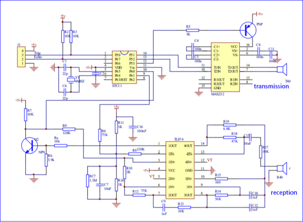
Circuit diagram of ultrasonic sensor:
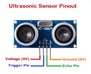
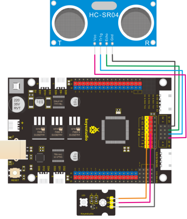
5.Connection Diagram:
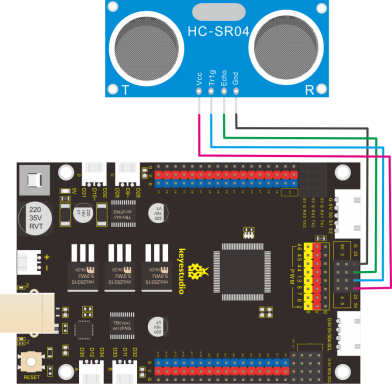
Wiring guide:
Ultrasonic sensor keyestudio V5 Sensor Shield
VCC → 5v(V)
Trig → 22(S)
Echo → 23(S)
Gnd → Gnd(G)
6.Test Code:
/*
  keyestudio smart motorhome
  lesson 15.1
  Ultrasonic sensor
  http://www.keyestudio.com
*/
//Ultrasonic Sensor
#define EchoPin  23  //ECHO to D23
#define TrigPin  22  //TRIG to D22
float dis;
void setup() {
  Serial.begin(9600);
  pinMode(EchoPin, INPUT);  // set pin ECHO to INPUT
  pinMode(TrigPin, OUTPUT);  //set pin TRIG to OUTPUT

}

void loop () {
  digitalWrite(TrigPin, LOW);
  delayMicroseconds(2);
  digitalWrite(TrigPin, HIGH);  //trigger TrigPin at least 10us high level
  delayMicroseconds(10);
  digitalWrite(TrigPin, LOW);
  dis = pulseIn(EchoPin, HIGH) / 2 / 29.1;   //calculate distance
  delay(50);  //delay in 50ms
  Serial.print("distance: ");
  Serial.print(dis);
  Serial.println("cm");
}
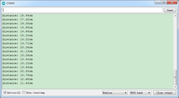
8.Test Result:
Upload code to development board, open serial monitor and set baud rate to 9600. The serial monitor shows the distance, and unit is cm. The value reduces when covering the ultrasonic sensor.
9.Code Explanation:
int trigPin- this pin is defined to transmit ultrasonic waves, generally output.
int echoPin - this is defined as the pin of reception, generally input
$$ cm = (duration/2) / 29.1 $$
$$ inches = (duration/2) / 74 $$
We can calculate the distance by using the following formula:
$$ Distance = (TravelTime/2) * SoundSpeed $$ The speed of sound is: 343m/s = 0.0343 cm/uS = 1/29.1 cm/uS
Or in inches: 13503.9in/s = 0.0135in/uS = 1/74in/uS
We need to divide the traveltime by 2 because we have to take into account that the wave was sent, hit the object, and then returned back to the sensor.
10.Extension Practice:
We’ve known how to detect the distance, next, let’s try to control an LED with detected distance Value.
Connect an LED module at D13
/*
  keyestudio smart motorhome
  lesson 15.2
  Ultrasonic sensor
  http://www.keyestudio.com
*/
//Ultrasonic Sensor
#define EchoPin  23  //ECHO to D23
#define TrigPin  22  //TRIG to D22
const int LED = 13;  //led pin to D13
volatile int distance;
void setup() {
  Serial.begin(9600);
  pinMode(EchoPin, INPUT);  //set pin ECHO to INPUT
  pinMode(TrigPin, OUTPUT);  //set pin TRIG to OUTPUT
  pinMode(LED, OUTPUT);
}

void loop () {
  distance = get_distance();  //set distance to variable distance
  Serial.println(distance);
  if (distance < 10) {
    digitalWrite(LED, HIGH);
  }
  else {
    digitalWrite(LED, LOW);
  }
}

int get_distance() {  //detect distance by ultrasonic sensor
  int dis;
  digitalWrite(TrigPin, LOW);
  delayMicroseconds(2);
  digitalWrite(TrigPin, HIGH);  //trigger TRIG at least 10us high level
  delayMicroseconds(10);
  digitalWrite(TrigPin, LOW);
  dis = pulseIn(EchoPin, HIGH) / 58;   //calculate distance
  delay(10);  //delay in 50ms
  return dis;
}
Upload the above code to development board. Do you find LED on when covering ultrasonic sensor by hand?
Project 16: 1602 LCD Display
1.Description:
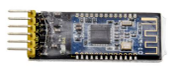
With I2C communication module, this is a display module that can show 2 lines with 16 characters per line.
It shows blue background and white word and connects to I2C interface of MCU, which highly save the MCU resources.
On the back of LCD display, there is a blue potentiometer for adjusting the backlight. The communication address defaults to 0x27.
The original 1602 LCD can start and run with 7 IO ports, but ours is built with ARDUINOIIC/I2C interface, saving 5 IO ports. Alternatively, the module comes with 4 positioning holes with a diameter of 3mm, which is convenient for you to fix on other devices.
Notice that when the screen gets brighter or darker, the characters will become more visible or less visible.
2.Specification:
I2C address: 0x27
Backlight (blue, white)
Power supply voltage: 5V
Adjustable contrast
GND: A pin that connects to ground
VCC: A pin that connects to a +5V power supply
SDA: A pin that connects to analog port 20 for IIC communication
SCL: A pin that connects to analog port 21 for IIC communication
3.Component:
Keyestudio MEGA 2560 Smart Development Board*1 |
Keyestudio I2C1602 Display *1 |
4pin F-F Dupont Line *1 |
|---|---|---|
|
|
|
USB Cable*1 |
6-Slot AA Battery Holder |
|
|
|


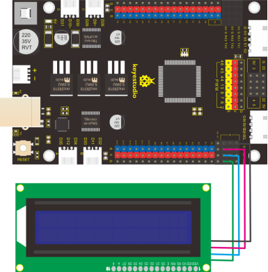
4.Connection Diagram:
Note: the pin GND, VCC, SDA and SCL of 1602LCD module are connected to GND(-), 5V(+), SDA and SCL.
5.Test Code:
/*
  keyestudio smart motorhome
  lesson 16.1
  I2C 1602
  http://www.keyestudio.com
*/
#include <Wire.h>
#include <LiquidCrystal_I2C.h> // includes the LiquidCrystal_I2C Library
LiquidCrystal_I2C lcd(0x27, 16, 2); // set the LCD address to 0x27 for a 16 chars and 2 line display

void setup() {
  lcd.init();
  // Print a message to the LCD.
  lcd.backlight();  //set backlight
  lcd.setCursor(0,0); //set cursor at the first row and first column
  lcd.print("Hello, World!"); //display "Hello, World!"
  lcd.setCursor(0,1); //at the second row and first column
  lcd.print("Hello, Keyes!"); //show "Hello, Keyes!"
}

void loop () {

}
6.Test Result:
Upload code, wire up according to connection diagram and power on. 1602 LCD will display“Hello World!”at the first row and show“Hello Keyes!”at the second row.
Note: wire up connection diagram, upload code and power on. You can adjust the potentiometer on the back of 1602LCD display module to display the character strings
Project 17: 2812 Light Strip
1.Description:
This module is an intelligent controlled LED light source that integrates the control circuit and light-emitting circuit.
Each LED shape is as same as a 5050LED bead. Each element is a pixel. Each pixel interior includes not only intelligent digital port data latch and signal reshaping amplification drive circuit, but also a precision internal oscillator and a 12V programmable constant current control part, effectively ensuring the highly consistency of the pixel point light color.
The data transfer protocol uses single RZ (return-to-zero) communication mode. After the pixel power-on to reset, the DI port receives data from controller, the first 24bit data is extracted by the first pixel, and then sent to the data latch inside the pixel. After being amplified by the internal shaping processing circuit, the remaining data will be forwarded to the next cascade pixel point through the DO port of the LED.
The signal will be reduced by 24bit for each pixel point transmission.
The pixel point adopts automatic transfer technology so that the number of cascade pixel are only limited by signal transmission speed rather than signal transmission.
2.Specification:
LED: WS2812
Working voltage: DC 5V
Working current: 40mA*10*2=8000mA (maximum) (each RGB lamp current 40mA)
Wiring mode: G-GND, V-VCC (DC 5V), DI (signal input terminal), DO (signal output terminal, used in cascade connection)
3.Component:
Keyestudio MEGA 2560 Smart Development Board*1 |
Full color WS2812B LED Light Strip with 5V 5050 Light Beads |
3pin F-F 26AWG Dupont Line *1 |
|---|---|---|
|
|
|
USB Cable*1 |
6-Slot AA Battery Holder |
|
|
|


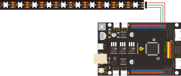
4.Connection Diagram:
Note: the pin GND, VCC and DI of 8x16 LED panel are interfaced with the pin -(GND), +(VCC)and 53 of sensor expansion board.
5.Test Code
/*
  keyestudio smart motorhome
  lesson 17.1
  2812 led
  http://www.keyestudio.com
*/
#include <Adafruit_NeoPixel.h>
Adafruit_NeoPixel rgb_2812 = Adafruit_NeoPixel(10, 53, NEO_GRB + NEO_KHZ800); //dset the port of 10 pcs lights to 53, with GRB mode

void setup() {
  rgb_2812.begin();
}

void loop () {

  for (int i = 0; i <= 9; i++) {
    rgb_2812.setPixelColor(i,255,0,0);  //the first light shows red color
    rgb_2812.show();                    //show
    delay(50);
  }
  for (int i = 9; i >= 0; i--) {
    rgb_2812.setPixelColor(i, 0,0,0);   //the first light turns off
    rgb_2812.show();                    //show
    delay(50);
  }

  for (int i = 0; i <= 9; i++) {
    rgb_2812.setPixelColor(i,0,255,0);  //the first light shows green color
    rgb_2812.show();                    //show
    delay(50);
  }
  for (int i = 9; i >= 0; i--) {
    rgb_2812.setPixelColor(i, 0,0,0);   //the first light turns off
    rgb_2812.show();                    //display
    delay(50);
  }

  for (int i = 0; i <= 9; i++) {
    rgb_2812.setPixelColor(i,0,0,255);  //the first light shows blue color
    rgb_2812.show();                    //show
    delay(50);
  }
  for (int i = 9; i >= 0; i--) {
    rgb_2812.setPixelColor(i, 0,0,0);   //the first light turns off
    rgb_2812.show();                    //show
    delay(50);
  }

}
6.Test Result:
Upload code and power on. 2812 light strip shows red, green and blue color.
7.Project Extension:
show gradient colour
/*
  keyestudio smart motorhome
  lesson 17.2
  2812 led
  http://www.keyestudio.com
*/
#include <Adafruit_NeoPixel.h>
Adafruit_NeoPixel rgb_2812 = Adafruit_NeoPixel(10, 53, NEO_GRB + NEO_KHZ800); //set the port of 10 pcs lights to 53, with GRB mode

void setup() {
  rgb_2812.begin();
}

void loop () {
  rainbow(20);  //keep gradient color for 20ms

}

void rainbow(uint8_t wait) {
  uint16_t i, j;
  for (j = 0; j < 256; j++) {
    for (i = 0; i <= 9; i++) {
      rgb_2812.setPixelColor(i, Wheel((i + j) & 255));
    }
    rgb_2812.show(); //display
    delay(wait);
  }
}

uint32_t Wheel(byte WheelPos) { //set color
  if (WheelPos < 85) {
    return rgb_2812.Color(WheelPos * 3, 255 - WheelPos * 3, 0);
  }
  else if (WheelPos < 170) {
    WheelPos -= 85;
    return rgb_2812.Color(255 - WheelPos * 3, 0, WheelPos * 3);
  }
  else {
    WheelPos -= 170;
    return rgb_2812.Color(0, WheelPos * 3, 255 - WheelPos * 3);
  }
}
Project 18 Motor Driving and Speed Control
1.Description:
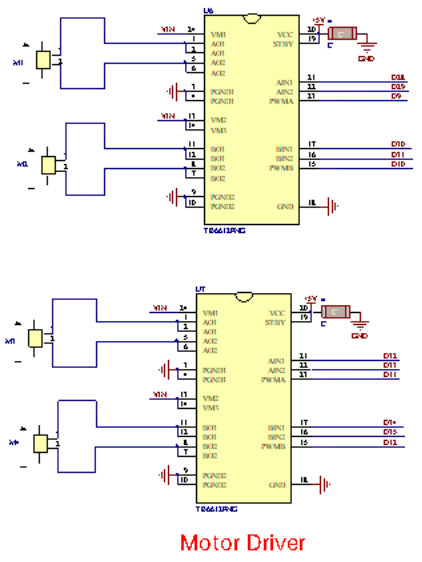
There are many ways to drive the motor. Our robot car uses the most commonly used TB6612FNG. TB6612FNG is an excellent high-power motor driver IC produced by STMicroelectronics.
It has large current MOSFET-H bridge structure and can directly drive two motors simultaneously. We apply the design of TB6612FNG circuit to development board, which reduces the technical difficulty of using and driving the motor.
Schematic Diagram
2.Specification
Logic part input voltage: DC5V
Driving part input voltage: DC 7-12V
Working temperature: -20~85℃
Power supply voltage: VM = 15V max, VCC = 2.7-5.5V
Output current: Iout = 1.2A (average) / 3.2A (peak)
Standby control to save power Clockwise/counterclockwise/short brake/stop motor control mode
Built-in thermal shutdown circuit and low voltage detection circuit
Filter capacitors on two power lines
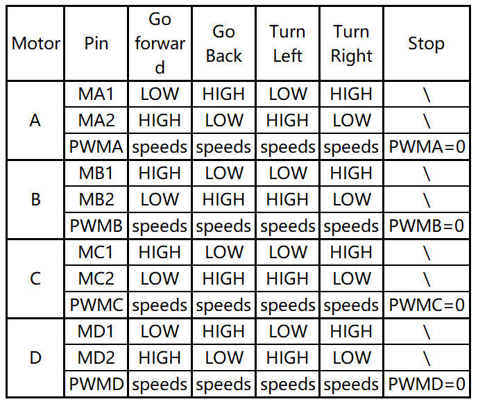
3.Working Principle
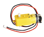
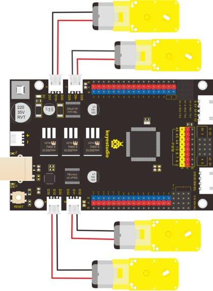
According to the above diagram of motor driver board, we know that speed control pins of motor A, B, C and D are D12, D11, D9 and D10; in the meanwhile, their direction control pins are D35 and D34, D33 and D32, D29 and D28, D31 and D30.
In the following chart, we also know how to control the speed of four motors via digital and PWM ports
PWM value is in the range of 0-255, the larger the number we set, the faster the motor rotates. ( We will drive a motor, therefore, speeds can be set a value in0~255)
4.Component:
MEGA 2560 Smart Development Board*1 |
4.5V 200r Motor*4 |
|---|---|
|
|
USB Cable*1 |
6-Slot AA Battery Holder*1 |
|
|


5.Connection Diagram:
6.Test Code:
/*
  keyestudio smart motorhome
  lesson 18.1
  motor
  http://www.keyestudio.com
*/
//define the pins of motor
const int Motor1 = 31;
const int Motor2 = 30;
const int PWM = 10;

void setup() {
  //set ports of motor to OUTPUT
  pinMode(Motor1, OUTPUT);
  pinMode(Motor2, OUTPUT);

}

void loop () {
  //rotate anticlockwise for 1
  digitalWrite(Motor1, HIGH);
  digitalWrite(Motor2, LOW);
  analogWrite(PWM, 100);
  delay(2000);
  //rotate clockwise for 1s
  digitalWrite(Motor1, LOW);
  digitalWrite(Motor2, HIGH);
  analogWrite(PWM, 100);
  delay(2000);
  //stop 1s
  analogWrite(PWM, 0);
  delay(1000);
}
7.Test Result:
Upload code and power on. The motor rotates clockwise for 2s, anticlockwise for 2s and stops for 1s.
8.Code Explanation:
digitalWrite(Motor,LOW); the rotation direction of motor is decided by the high/low level and and the pins that decide rotation direction are digital pins.
analogWrite(PWM,100); the speed of motor is regulated by PWM, and the pins that decide the speed of motor must be PWM pins.
9.Extension Practice:
Control car’s motion via rotation direction of motors.
/*
  keyestudio smart motorhome
  lesson 18.2
  motor
  http://www.keyestudio.com
*/
//define the pins of motor A,B,C and D
const int MA1 = 35;
const int MA2 = 34;
const int PWMA = 12;

const int MB1 = 33;
const int MB2 = 32;
const int PWMB = 11;

const int MC1 = 29;
const int MC2 = 28;
const int PWMC = 9;

const int MD1 = 31;
const int MD2 = 30;
const int PWMD = 10;

void setup() {
  //set the pins of motor to OUTPUT
  pinMode(MA1, OUTPUT);
  pinMode(MA2, OUTPUT);

  pinMode(MB1, OUTPUT);
  pinMode(MB2, OUTPUT);

  pinMode(MC1, OUTPUT);
  pinMode(MC2, OUTPUT);

  pinMode(MD1, OUTPUT);
  pinMode(MD2, OUTPUT);

}

void loop () {
  //go forward for 1s
  advance();
  delay(1000);
  //go back for 1s
  back();
  delay(1000);
  //turn left for 1s
  turnleft();
  delay(1000);
  //turn right for 1s
  turnright();
  delay(1000);
  //stop 1s
  Stop();
  delay(1000);
}

void advance() {    //go forward
  // motor A rotates clockwise
  digitalWrite(MA1, HIGH);
  digitalWrite(MA2, LOW);
  analogWrite(PWMA, 150);
  //motor B rotates clockwise
  digitalWrite(MB1, LOW);
  digitalWrite(MB2, HIGH);
  analogWrite(PWMB, 150);
  //motor C rotates clockwise
  digitalWrite(MC1, LOW);
  digitalWrite(MC2, HIGH);
  analogWrite(PWMC, 150);
  //motor D rotates clockwise
  digitalWrite(MD1, HIGH);
  digitalWrite(MD2, LOW);
  analogWrite(PWMD, 150);
}

void back() {   //go back
  //motor A rotates anticlockwise
  digitalWrite(MA1, LOW);
  digitalWrite(MA2, HIGH);
  analogWrite(PWMA, 150);
  //motor B rotates anticlockwise
  digitalWrite(MB1, HIGH);
  digitalWrite(MB2, LOW);
  analogWrite(PWMB, 150);
  //motor C rotates anticlockwise
  digitalWrite(MC1, HIGH);
  digitalWrite(MC2, LOW);
  analogWrite(PWMC, 150);
  //motor D rotates anticlockwise
  digitalWrite(MD1, LOW);
  digitalWrite(MD2, HIGH);
  analogWrite(PWMD, 150);
}

void turnleft() {   //turn left
  //motor A rotates clockwise
  digitalWrite(MA1, HIGH);
  digitalWrite(MA2, LOW);
  analogWrite(PWMA, 150);
  //motor B rotates anticlockwise
  digitalWrite(MB1, HIGH);
  digitalWrite(MB2, LOW);
  analogWrite(PWMB, 150);
  //motor C rotates anticlockwise
  digitalWrite(MC1, HIGH);
  digitalWrite(MC2, LOW);
  analogWrite(PWMC, 150);
  //motor D rotates clockwise
  digitalWrite(MD1, HIGH);
  digitalWrite(MD2, LOW);
  analogWrite(PWMD, 150);
}

void turnright() {    //turn right
  //motor A rotates anticlockwise
  digitalWrite(MA1, LOW);
  digitalWrite(MA2, HIGH);
  analogWrite(PWMA, 150);
  //motor B rotates clockwise
  digitalWrite(MB1, LOW);
  digitalWrite(MB2, HIGH);
  analogWrite(PWMB, 150);
  //motor C rotates clockwise
  digitalWrite(MC1, LOW);
  digitalWrite(MC2, HIGH);
  analogWrite(PWMC, 150);
  //motor D rotates anticlockwise
  digitalWrite(MD1, LOW);
  digitalWrite(MD2, HIGH);
  analogWrite(PWMD, 150);
}

void Stop() {   //Car stops
  //set the speed of four motors to 0
  analogWrite(PWMA, 0);
  analogWrite(PWMB, 0);
  analogWrite(PWMC, 0);
  analogWrite(PWMD, 0);
}
Upload code and power on. The car goes forward 1s, back for 1s, turns left for 1s and right for 1s, then stops.
Project 19 Bluetooth Remote Control
1.Description:
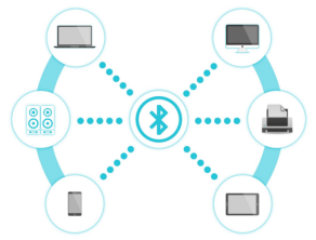
Bluetooth, a simple wireless communication module most popular since the last few decades and easy to use are being used in most of the battery-powered devices.
Over the years, there have been many upgrades of Bluetooth standard to keep fulfil the demand of customers and technology according to the need of time and situation.
Over the few years, there are many things changed including data transmission rate, power consumption with wearable and IoT Devices and Security System.
Here we are going to learn about HM-10 BLE 4.0 with Arduino Board. The HM-10 is a readily available Bluetooth 4.0 module. This module is used for establishing wireless data communication. The module is designed by using the Texas Instruments CC2540 or CC2541 Bluetooth low energy (BLE) System on Chip (SoC).
2.Specification :
1).Bluetooth protocol: Bluetooth Specification V4.0 BLE
2).No byte limit in serial port Transceiving
3).In open environment, realize 100m ultra-distance communication with iphone4s
4).Working frequency: 2.4GHz ISM band
5).Modulation method: GFSK(Gaussian Frequency Shift Keying)
6).Transmission power: -23dbm, -6dbm, 0dbm, 6dbm, can be modified by AT command.
7).Sensitivity: ≤-84dBm at 0.1% BER
8).Transmission rate: Asynchronous: 6K bytes ; Synchronous: 6k Bytes
9).Security feature: Authentication and encryption
10).Supporting service: Central & Peripheral UUID FFE0, FFE1
11).Power consumption: Auto sleep mode, stand by current 400uA~800uA, 8.5mA during transmission.
12).Power supply: 5V DC
13).Working temperature: –5 to +65 Centigrade
3.Component:
Keyestudio MEGA 2560 Smart Development Board*1 |
Keyestudio HM-10 Bluetooth-4.0 V3 |
Keyestudio White LED Module*1 |
|---|---|---|
|
|
|
3pin F-F 26AWG Dupont Line |
USB Cable*1 |
6-Slot AA Battery Holder |
|
|
|
Prepare a smart cellphone |

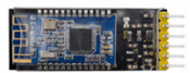


4.Connection Diagram:
1). STATE: state test pins, connected to internal LED, generally keep it unconnected.
2). RXD: serial interface, receiving terminal.
3). TXD: serial interface, transmitting terminal.
4). GND: Ground.
5). VCC: positive pole of the power.
6). EN/BRK: break connect, it means breaking the Bluetooth connection, generally, keep it unconnected.
(Notice Serial and Serial1)
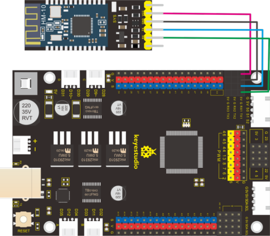
5.Test Code:
/*
  keyestudio smart motorhome
  lesson 19.1
  bluetooth
  http://www.keyestudio.com
*/
char ble_val;   //set variable ble_val

void setup() {
  Serial.begin(9600);   //set USB baud rate to 9600
  Serial1.begin(9600);  //set Bluetooth baud rate to 9600
}

void loop () {
  if (Serial1.available() > 0) // determine if there is data in the buffer of serial port
  {
    ble_val = Serial1.read();  //read the data saved in the buffer of serial port
    Serial.println(ble_val);  //serial port prints data
  }
}
Upload code to development board and insert Bluetooth module and wait for the command from cellphone.
6.Download APP:
The above code is used to read the received signals. Yet, we need to send signals.
Next, we download an App to send signals.
iOS System
1.Open App store
2.Search Motorhome and download it

The App page is shown below:

Turn on Bluetooth of your device, and click“connect”to search and pair Bluetooth.

Android System
Enter Google play store to search keyestudio motorhome, or go to link to download it :
https://play.google.com/store/apps/details?id=com.keyestudio.motorhome
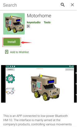
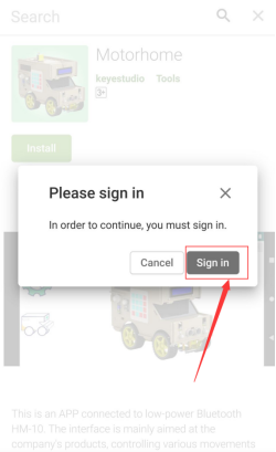
Note: Allow APP to access“location”in settings of your cellphone when connecting to Bluetooth module, otherwise, Bluetooth may not be connected.
Click icon to enter APP, as shown below;
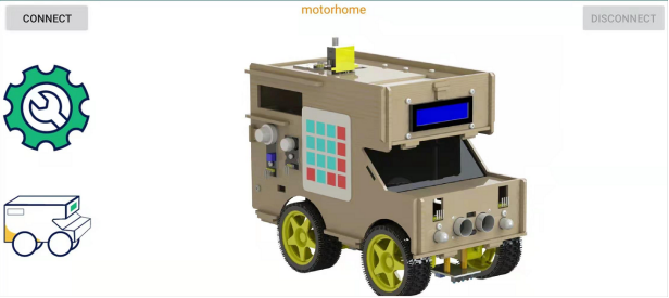
After connecting Bluetooth, plug in power and LED indicator of Bluetooth module will flash. Tap to search Bluetooth.
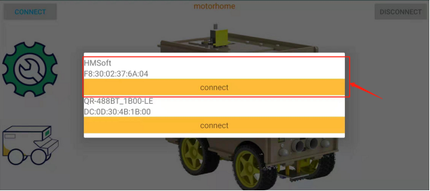
Click“connect”below HMSoft, then the Bluetooth will be connected and its LED indicator will be always on.
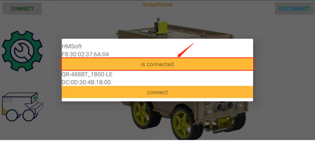
After connecting Bluetooth module and opening serial monitor and setting baud rate to 9600. Press icons on APP, and the corresponding characters are displayed as shown below:
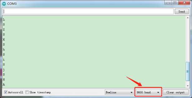
7.Code Explanation:
Serial.available():the number of left characters when back to buffer, this function is usually used to judge if there is data in buffer. Whenever Serial.available() is more than 0, serial will receive the data in serial monitor.
Serial.read(): read a Byte in buffer of serial. We can read the data sent with Serial.read(), for instance, some devices send data to Arduino through serial monitor.
Note: We use Serial and Serial1. Serial is used for Arduino monitor communication and Serial 1 is used for Bluetooth serial.
8.APP Interface:
Open App and we will see its main interface as follows:
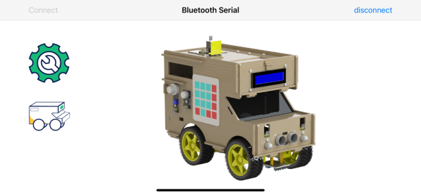
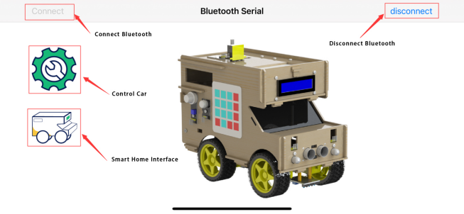
ICON |
FUNCTION |
|---|---|
|
connect Bluetooth |
|
disconnect Bluetooth |


 :enter control interface(as follows):
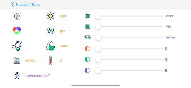
ICON |
FUNCTION |
|---|---|
|
turn on and off LED |
|
show 2812 light |
|
listen to music |
|
check humidity |
|
check ambient light brightness |
|
check the concentration of combustible gas |
|
check steam value |
|
check temperature |
|
view if there is someone around |
|
open and close door |
|
open and close roof window |
|
open and close the trunk of car |
|
make RGB show red color |
|
make RGB to show green color |
|
make RGB to show blue color |


Drag process bar to control the angle of servo and RGB brightness.
 : enter control interface(as follows):
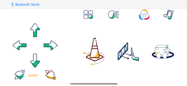
ICON |
FUNCTION |
|---|---|
|
go forward |
|
go back |
|
turn left |
|
turn right |
|
speed up and show speed value |
|
speed down and show speed value |
|
enter obstacle avoidance mode |
|
enter follow mode |
|
enter line tracking mode |


 : The motorhome shows the corresponding color if the“flower”icons are pressed:
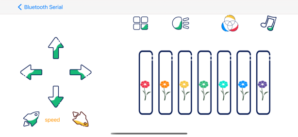
 : enter the following interface:
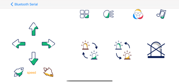
ICON |
FUNCTION |
|---|---|
|
display the color of 2812 light strip |
|
switch to the previous color |
|
turn off 2812 light |


 : enter the following page:
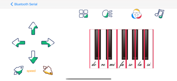
The motorhome will emit the corresponding sound when pressing“do,re,mi,fa,so,la,si.”
9.Extension Practice:
Next, we will turn on and off LED via Bluetooth commands.
Note: Allow APP to access“location”in settings of your cellphone when connecting to Bluetooth module, otherwise, Bluetooth may not be connected.
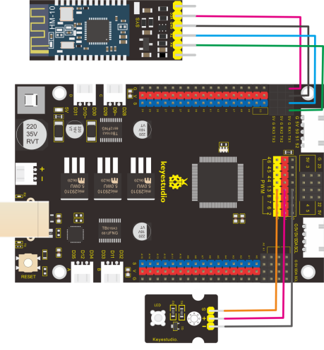
/*
  keyestudio smart motorhome
  lesson 19.2
  bluetooth
  http://www.keyestudio.com
*/
char ble_val;   //set variable to ble_val
#define LED    13    //led pin to D13
void setup() {
  Serial1.begin(9600);  //set Bluetooth baud rate to 9600
  pinMode(LED, OUTPUT); //set the pin of LED to OUTPUT

}

void loop () {
  if (Serial1.available() > 0) //determine if there is data in the buffer of Bluetooth serial port
  {
    ble_val = Serial1.read();  //read the data saved in the buffer of Bluetooth serial port
    if (ble_val == 'A') {
      digitalWrite(LED, HIGH);
    }
    else if (ble_val == 'H') {
      digitalWrite(LED, LOW);
    }
  }
}
Click “Write” on app to send “F” or “B” to control LED.
Project 20: Install Smart Motorhome
1.Component:
Picture |
Model |
Cable |
|
|---|---|---|---|
1 |
|
4*4 Membrane Keypad |
15cm 8pin M-F 26AWG Dupont Line |
2 |
|
Keyestudio PIR Motion Sensor |
20cm 3pin F-F 26AWG Dupont Line |
3 |
|
Keyestudio Analog Gas Sensor |
20cm 4pin F-F 26AWG Dupont Line |
4 |
|
keyestudio Power Amplifier Module |
20cm 3pin F-F 26AWG Dupont Line |
5 |
|
Keyestudio 180° 9G Servo |
\ |
6 |
|
Keyestudio Quick Connectors Line Tracking Sensor |
40cm 5pin XH2.54 to PH2.0 26AWG Dupont Line |
7 |
|
6-Slot AA Battery Holder |
\ |
8 |
|
HC-SR04 Ultrasonic Sensor |
35cm 4pin F-F 26AWG Dupont Line |
9 |
|
Keyestudio 10mm Highlight Full-color LED Module |
35cm 4pin F-F 26AWG Dupont Line |
10 |
|
Keyestudio I2C1602 LCD Module |
20cm 4pin 26AWG Dupont Line |
11 |
|
Keyestudio White LED Module |
20cm 3pin F-F 26AWG Dupont Line |
12 |
|
Keyestudio DHT11 Temperature and Humidity Sensor |
20cm 3pin F-F 26AWG Dupont Line |
13 |
|
Keyestudio Ambient TEMT6000 Sensor |
15cm 3pin F-F 26AWG Dupont Line |
14 |
|
Keyestudio Steam Sensor |
20cm 3pin F-F 26AWG Dupont Line |
15 |
|
Keyestudio Analog Rotation Potentiometer |
20cm 3pin F-F 26AWG Dupont Line |
16 |
|
Keyestudio Digital Push Button Module |
15cm 3pin F-F 26AWG Dupont Line |
17 |
|
5V WS2812B LED Light Strip with 5050 Light Beads |
15cm 3pin F-F 26AWG Dupont Line |
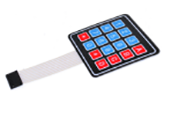

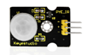

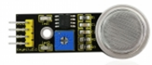

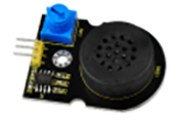

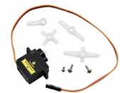
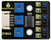

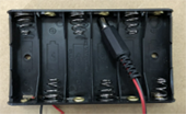


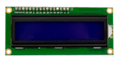

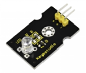


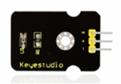


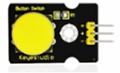

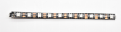
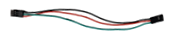
2.Precaution:
1).The front side of each board has a number, the back side is marked ”Back side”.
2).You don’t need to screw the nuts of proof window too tight
3).Be care to assemble the slot and top board in case they are broken
4).Initialize the servo before installing
5).Peel the thin film off the acrylic boards before assembling motorhome. In the subsequent projects, the wiring-up of sensors is the same as the previous wiring.
3.Set angles of servos:
Name |
Angle |
Port |
|---|---|---|
Servo 1 |
Rotate to 80° |
D6 |
Servo 2 |
Rotate to 0° |
D7 |
Servo3 |
Rotate to 0° |
D8 |
4.Connection Diagram
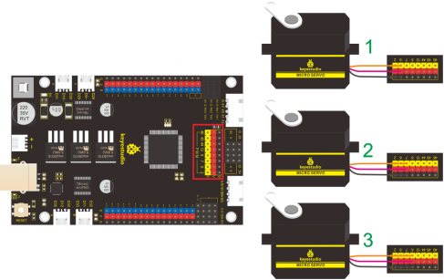
5.Test Code
#include <Servo.h>
Servo myservo1,myservo2,myservo3;  // create servo object to control a servo

void setup()
{
  Serial.begin(9600);
myservo1.attach(6);  // modify each pin to adjust
myservo2.attach(7);  // modify each pin to adjust
myservo3.attach(8);  // modify each pin to adjust
  myservo1.write(80);  // angle value
  delay(1000);
myservo2.write(0);  // angle value
  delay(1000);
myservo3.write(0);  // angle value
  delay(1000);
}

void loop()
{
}
6.Test Result
Interface servo with D6, D7 and D8 of board, upload code and wire up. Plug in power and press reset button, servo will automatically rotate the initial angle we set.
7.Installation Steps
1).Part 1
Components
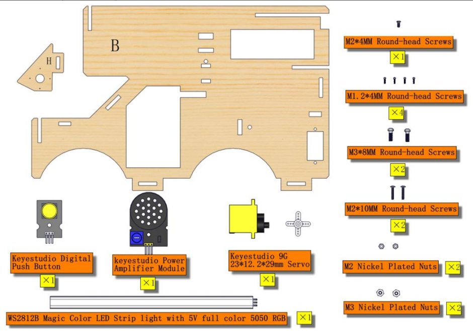
Install button sensor on the number 19 area of board B
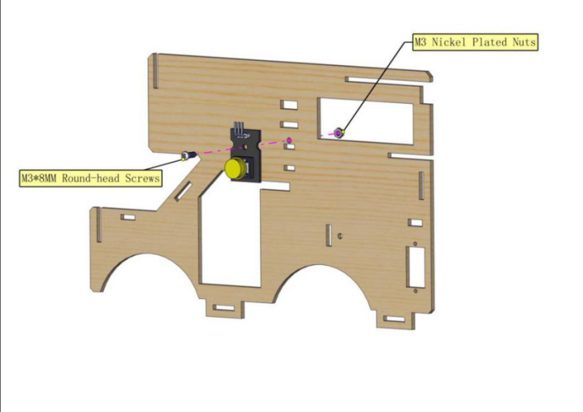
Mount power amplifier module at the number 4 area of board B,and rotate the potentiometer to the middle area.
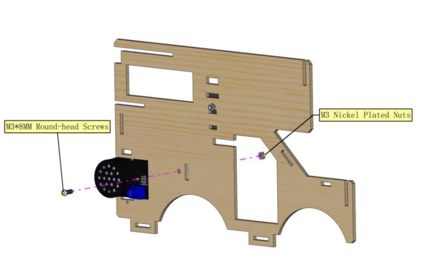
Initialize servo2 and fix it on the number 5 area of board B and notice the direction.
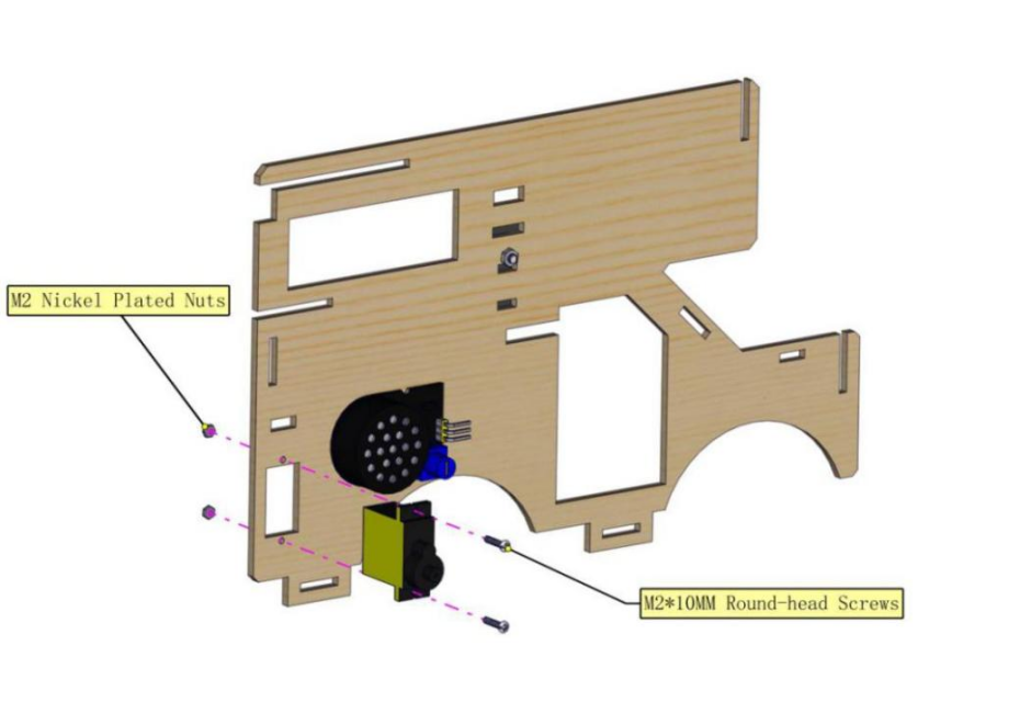
Fix the cross mount on the board H
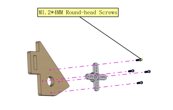
Use M2*4 screws from servo and mount board H onto servo.
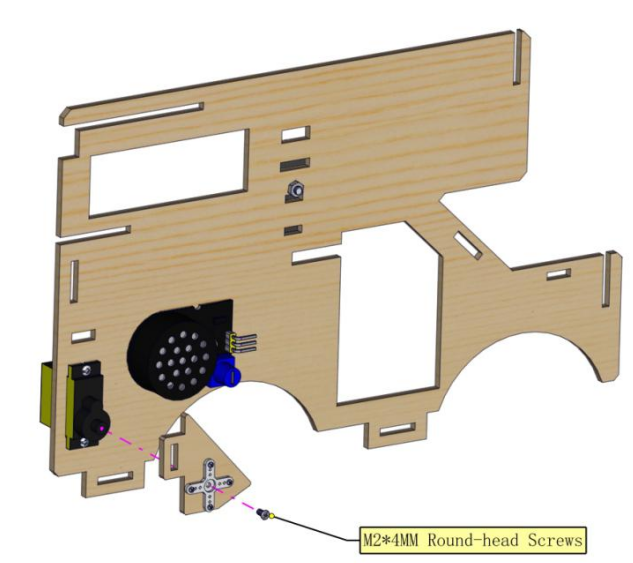
Install LED strip at the number 21 of board B.
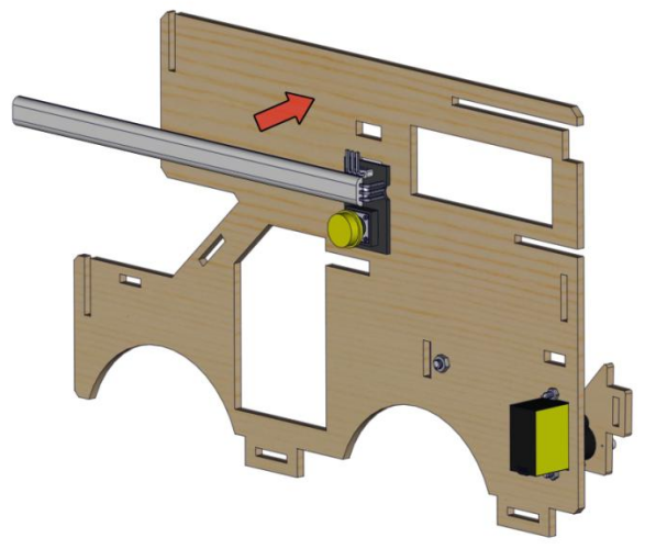
Assembled images
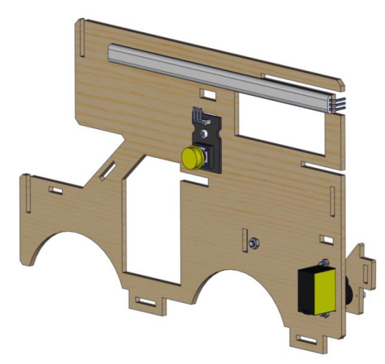
2).Part 2
Components
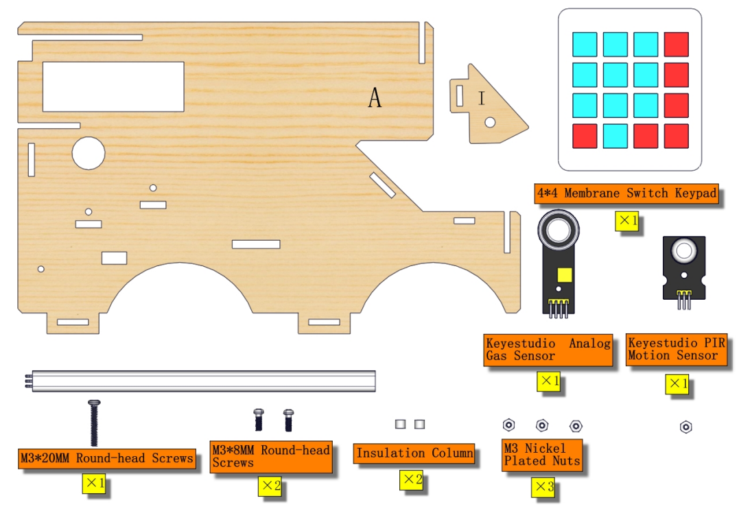
Mount gas sensor at number 3 area of board A
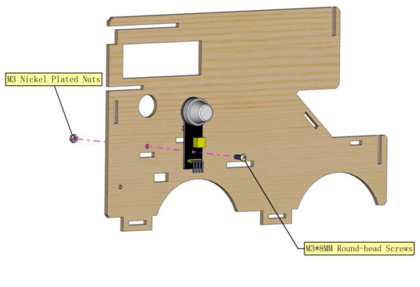
Assemble PIR motion sensor at number 2 of board A

Install LED strip at number 20 area of board A
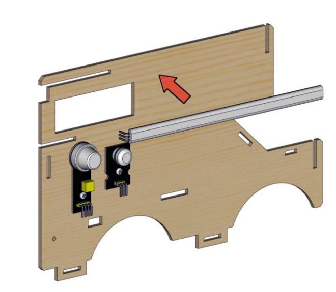
Fix 4*4 membrane keypad onto number 1 area of board A
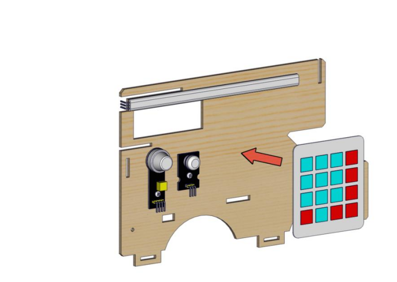
Assemble board I on board A
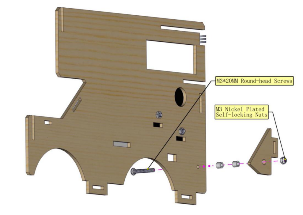
Assembled images
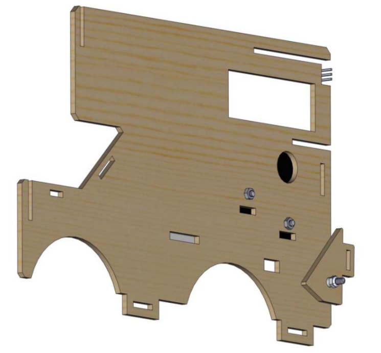
3).Part 3
Components
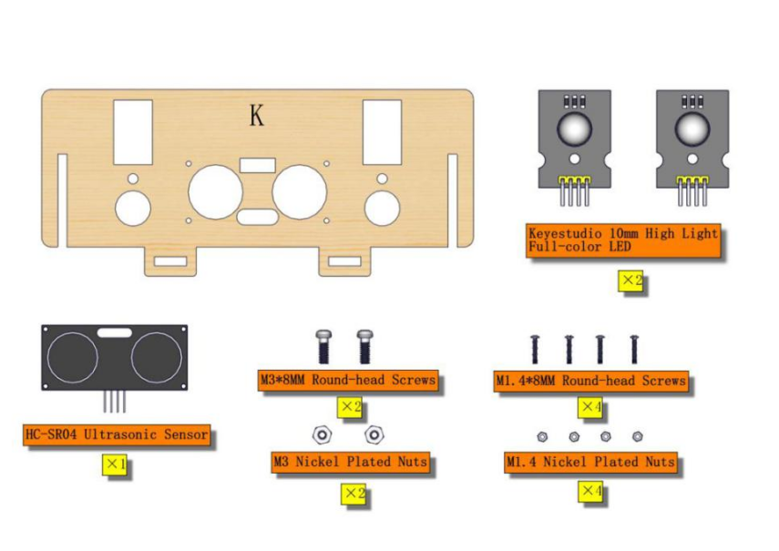
Wire up first
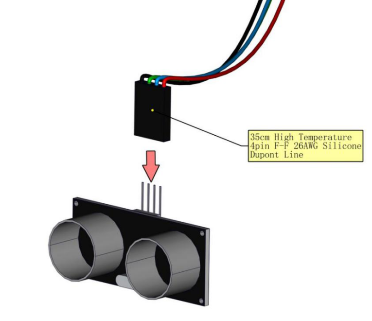
Install ultrasonic sensor onto number 8 area of board K
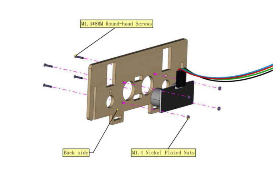
Wire up first
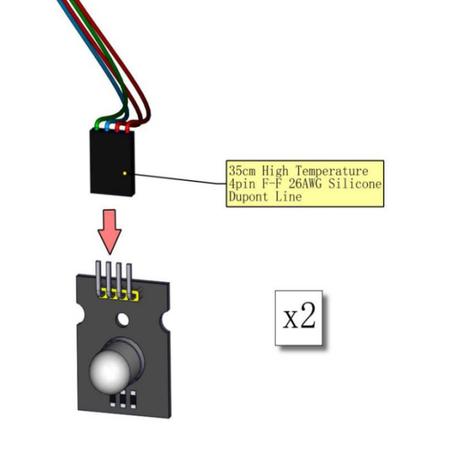
Install the full-color LED module onto number 9 and 10 area of board K
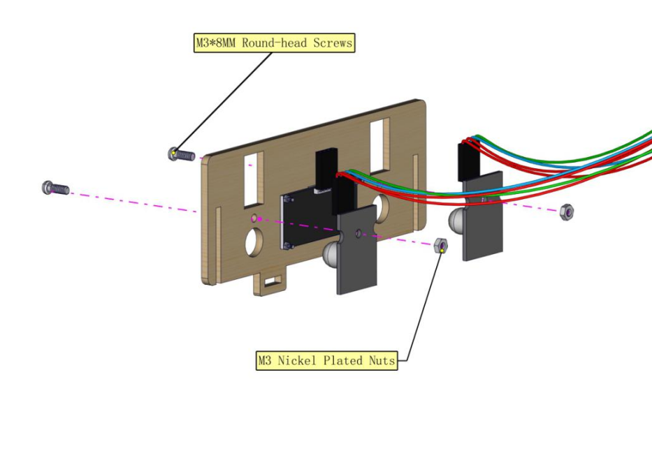
Assembled images
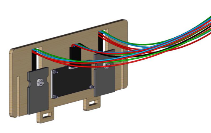
4).Part 4
Components
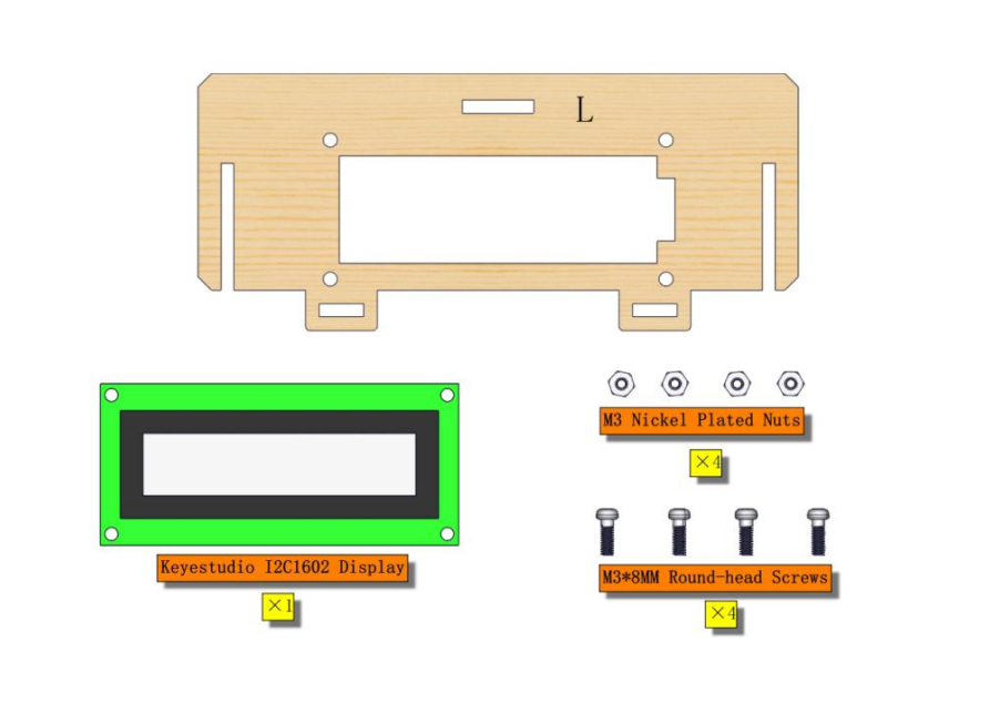
Mount the LCD display onto number 11 area of board L
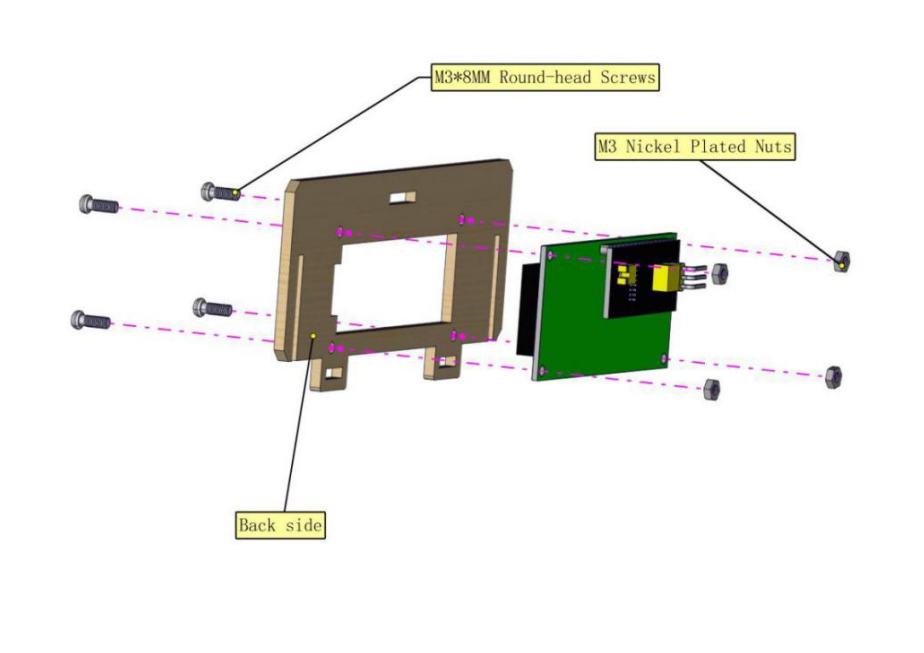
Assembled images
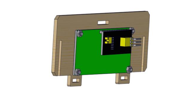
5).Part 5
Components
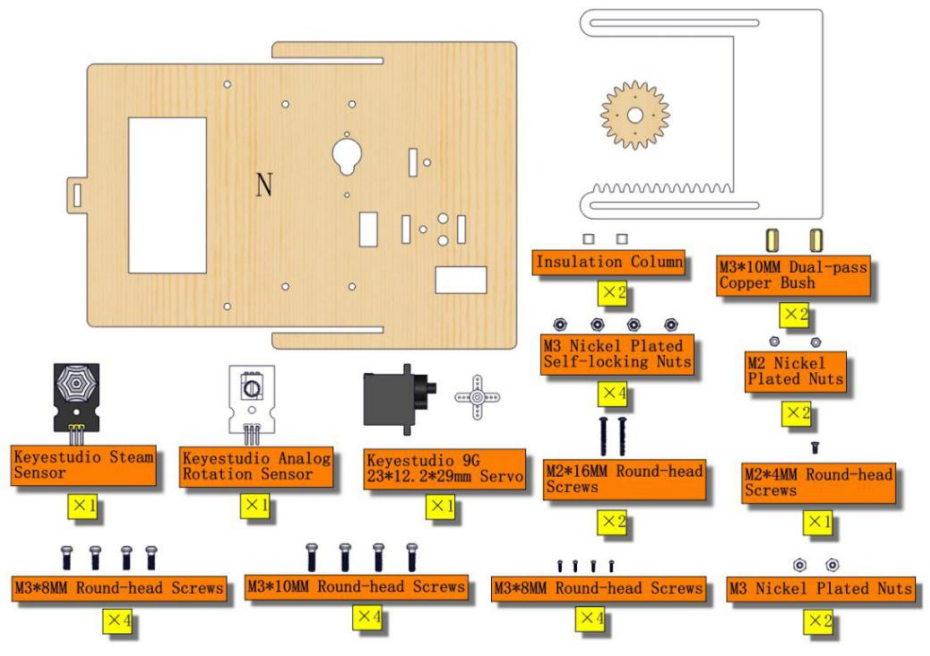
Respectively assemble rotary potentiometer and steam sensor at number 16 area and number 17 of board N
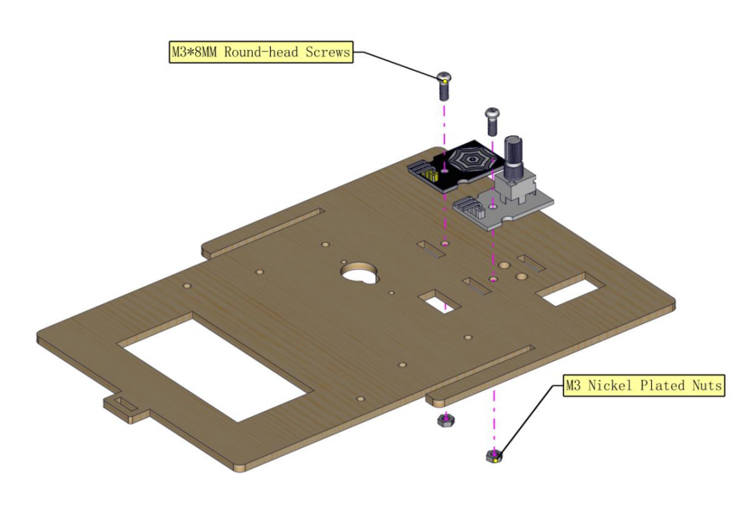
Initialize servo 1 and install it at number 19 area of board N
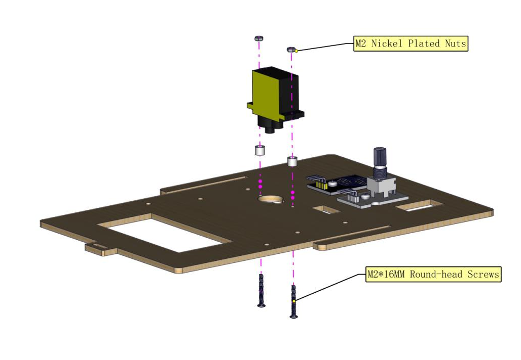
Fix servo cross mount onto gear of roof window with M2*4MM screws from servo
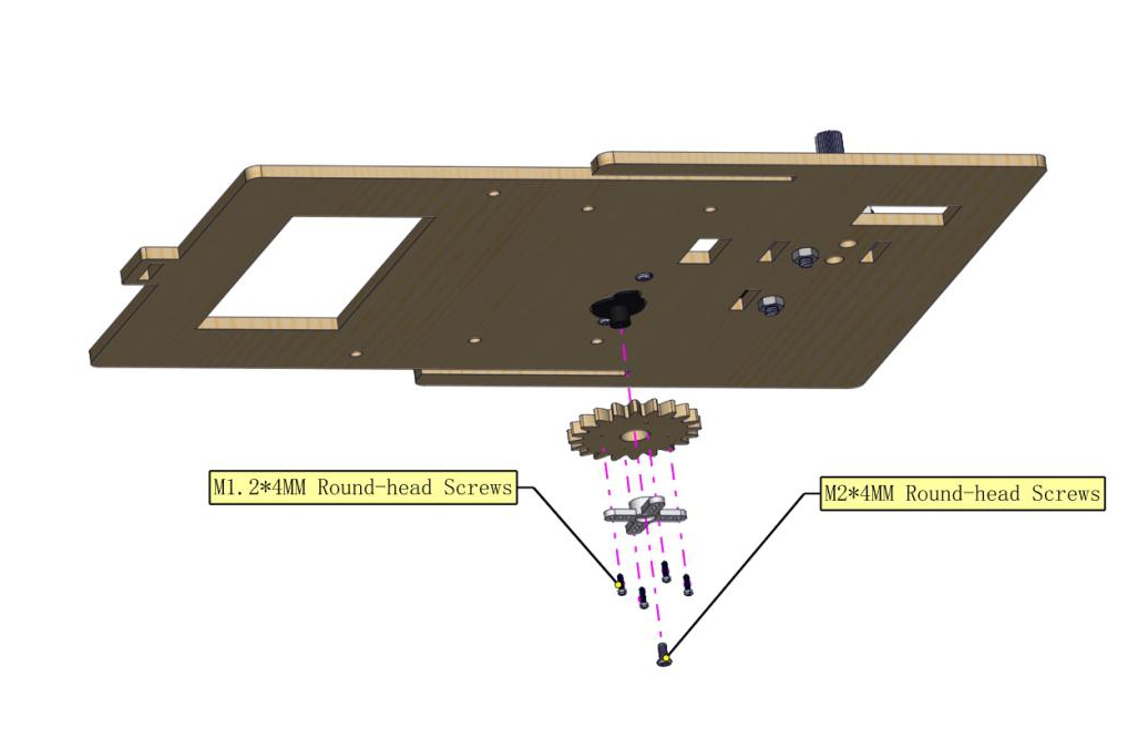
Install board O onto board N and don’t need to screw nuts tightly.
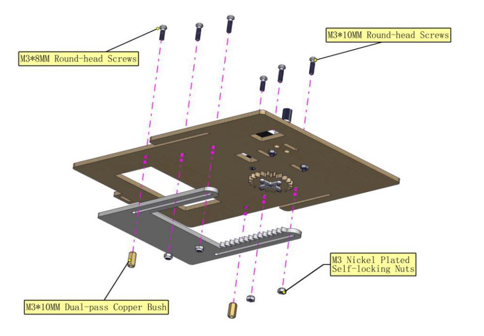
Assembled images
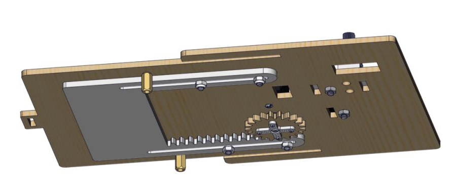
6).Part 6
Components
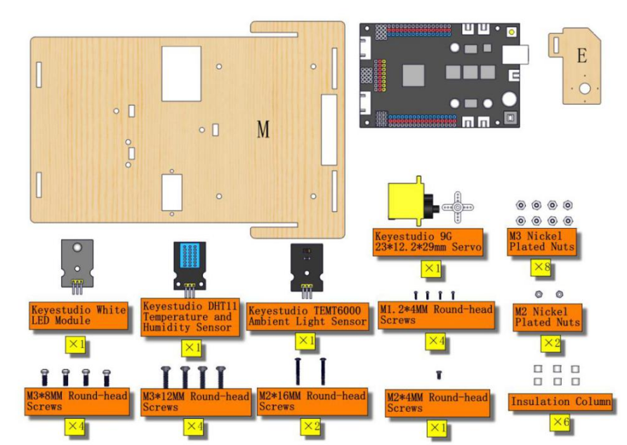
Respectively install temperature humidity sensor and ambient light sensor at number 14 area and number 15 area of board M.
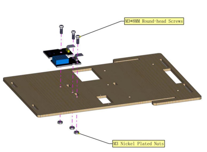
Fix white LED module onto number 12 area of board M
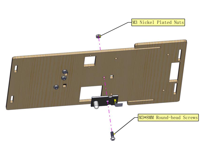
Adjust the angle of servo 3 and install it onto number 13 area.
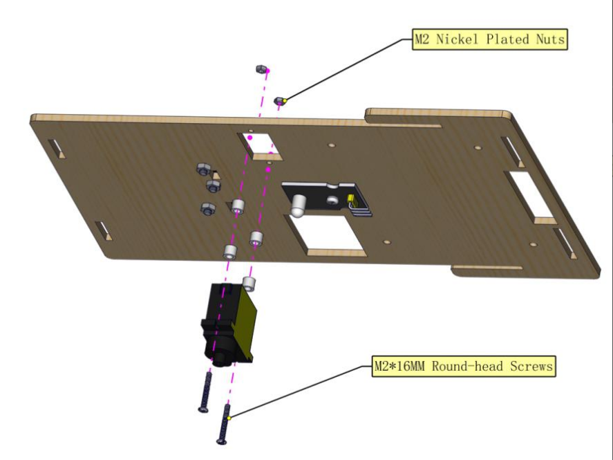
Fix servo cross onto board E
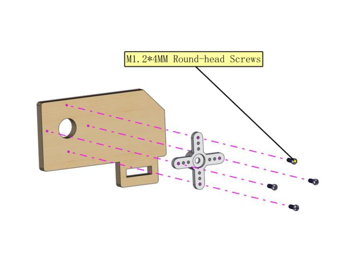
Use M2*4MM screws from servo to install board E onto servo
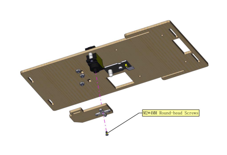
Fix control board onto M board
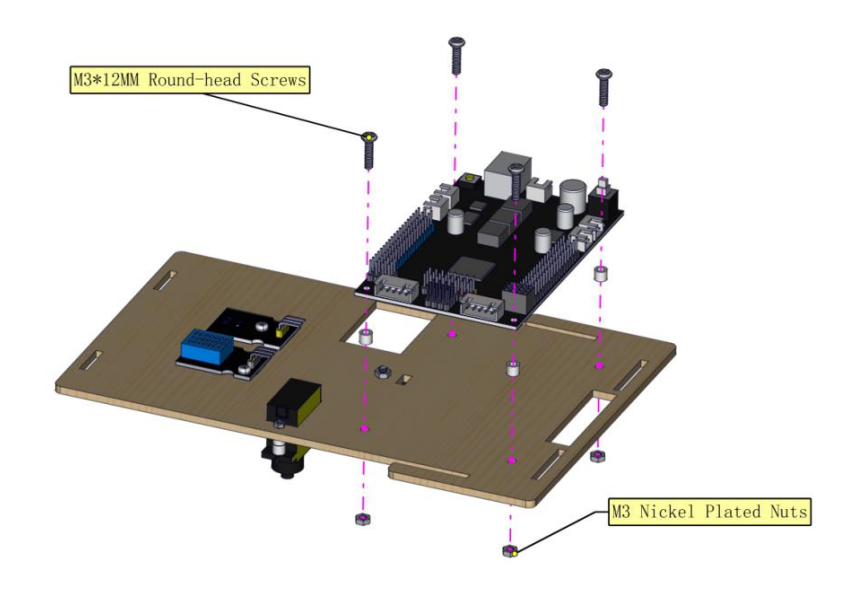
Assembled images
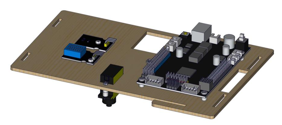
7).Part 7
Components
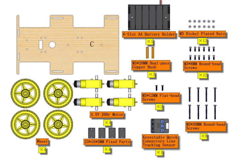
Assemble motor parts onto board C
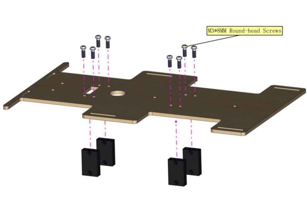
Install motors onto board and notice the direction of motors
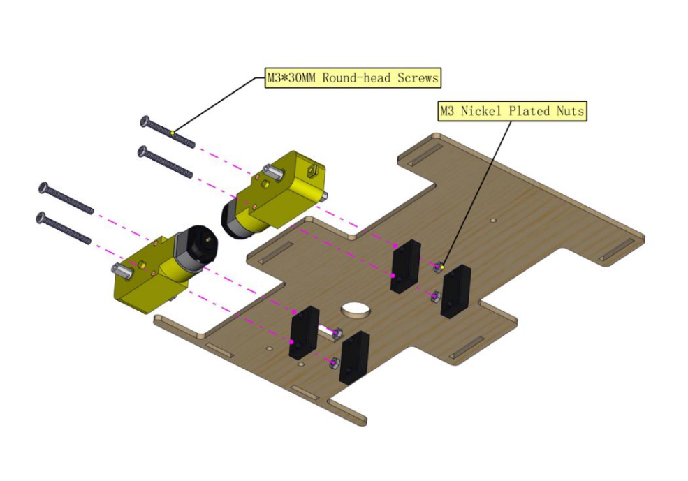
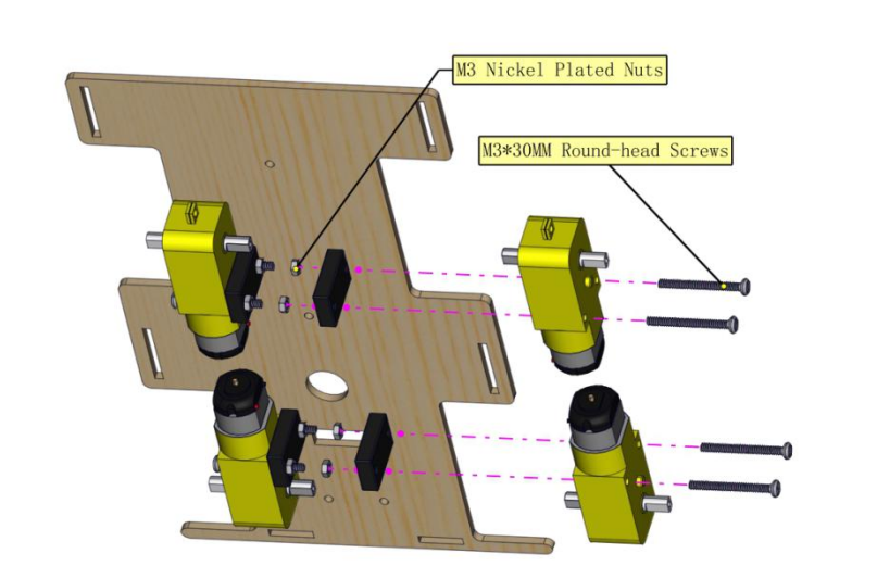
Install the wheels onto motor
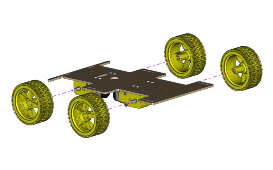
Assemble battery holder onto number 7 area of board C
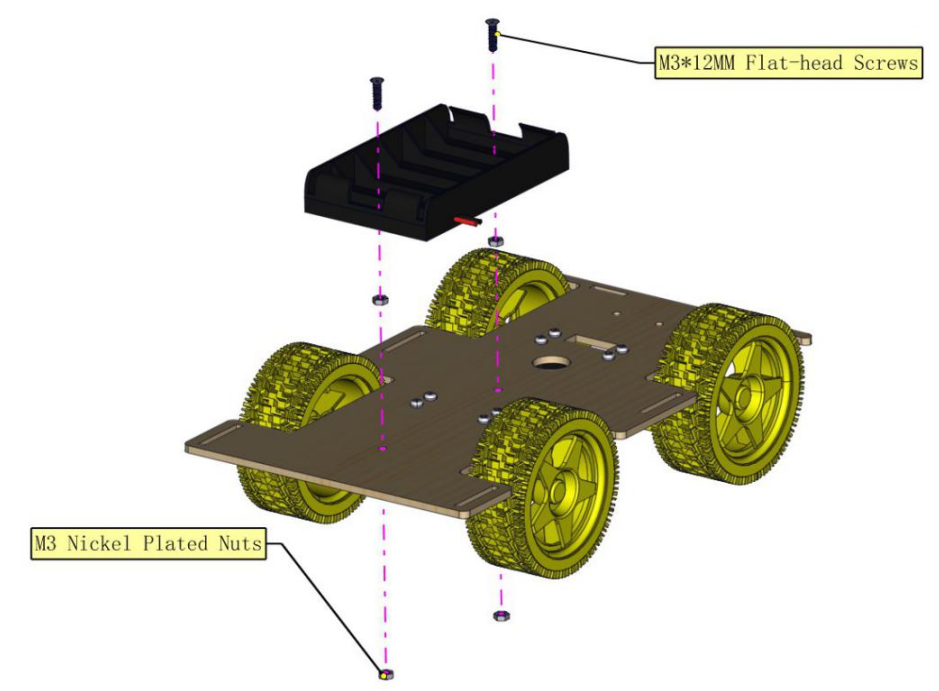
Mount line tracking sensor onto number 6 area of board C
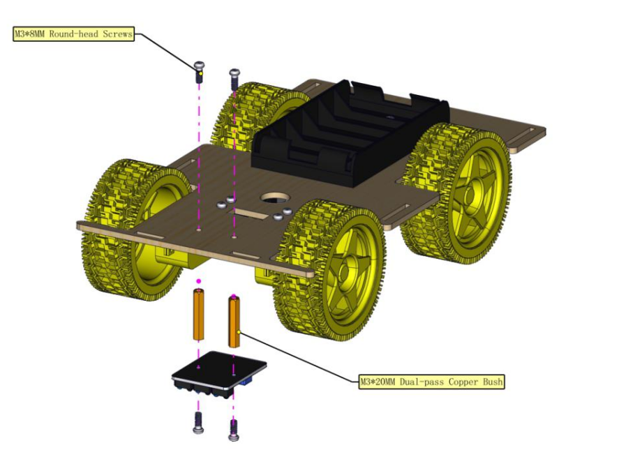
Assembled images
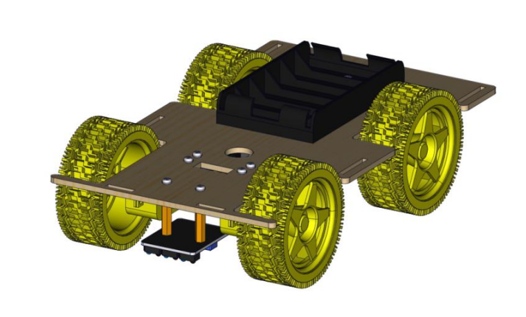
8).Part 8
Be patient please when you have difficulty in inserting them.
Use the bigger slots to install
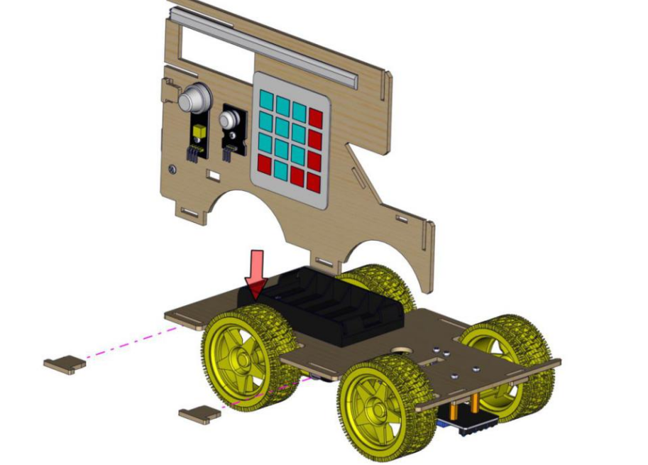
Use the bigger slots to install
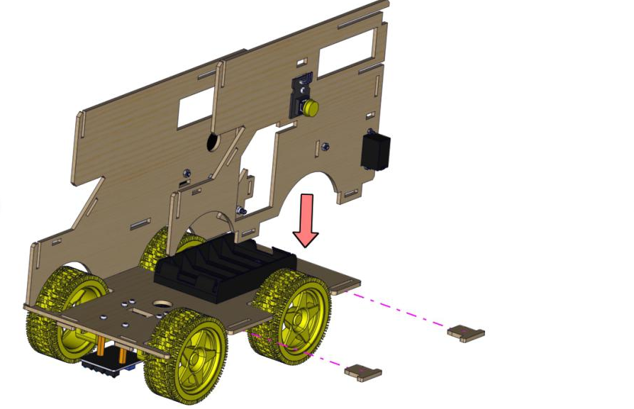
Make the side marked letters on board G face upward
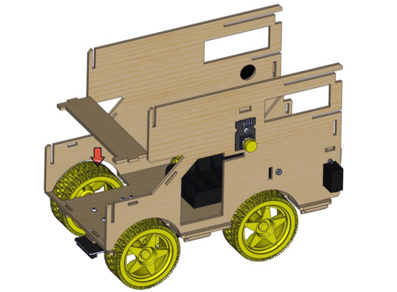
Make the side marked letters on board P face forward
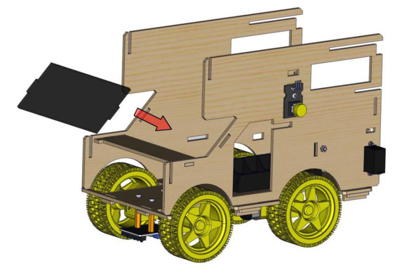
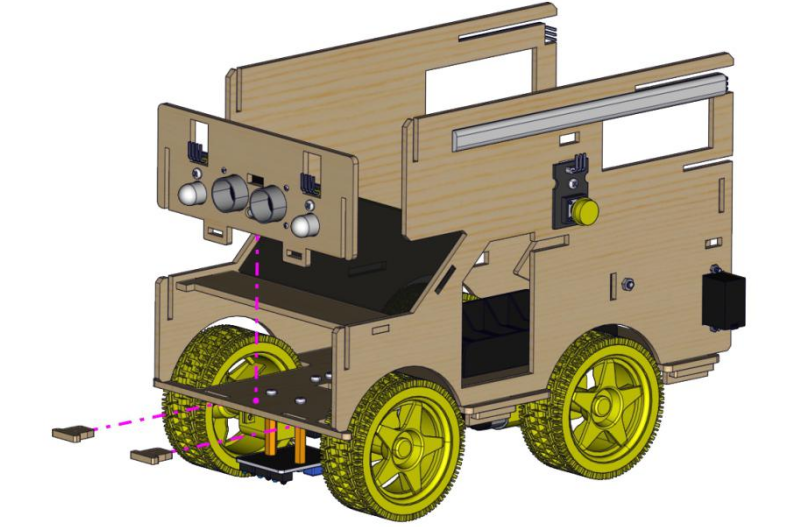
Be careful to install board because its protruding part is weak.
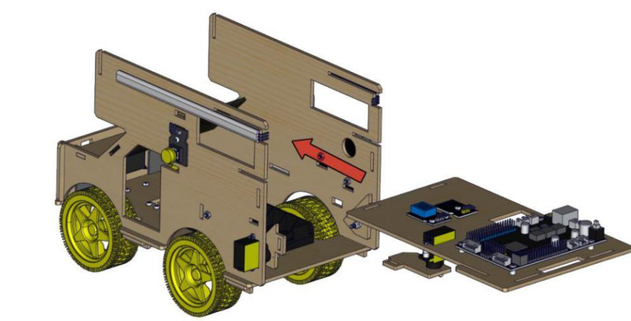
You need to remove board E, then install board F and slot.
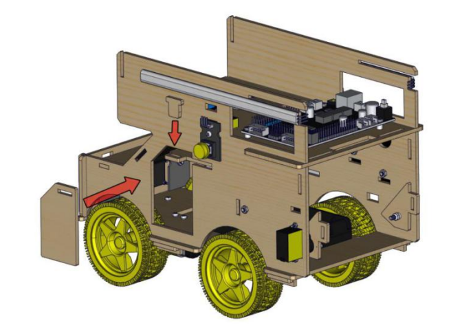
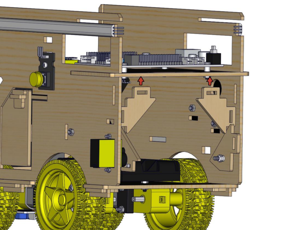
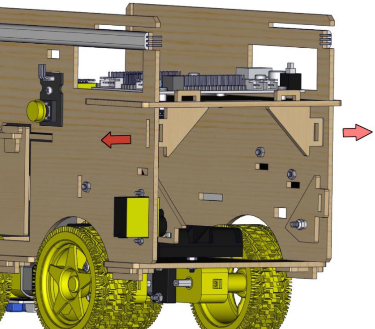
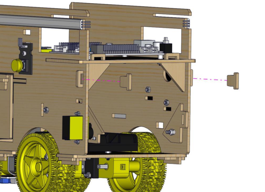
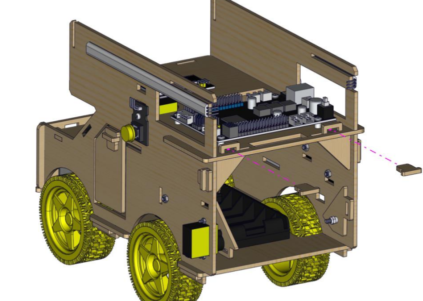
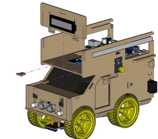
9).Wiring Up
According to diagram to wire up
-1681697254550-353.jpg)
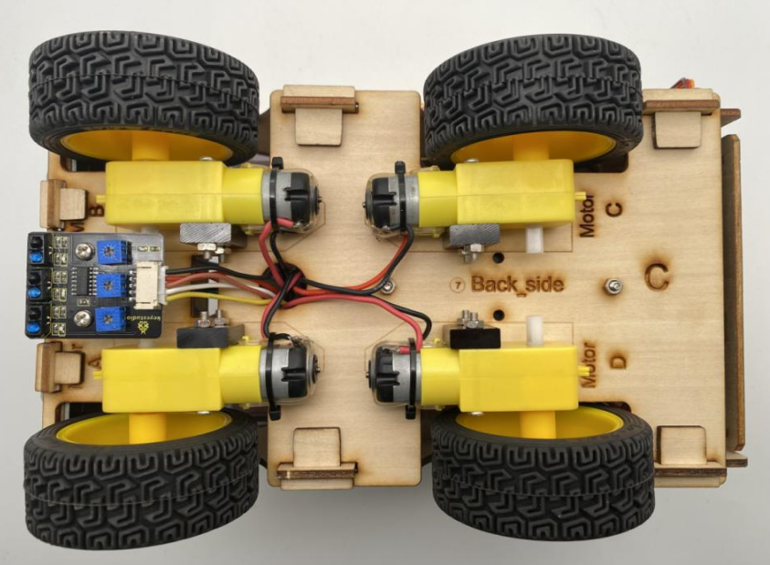
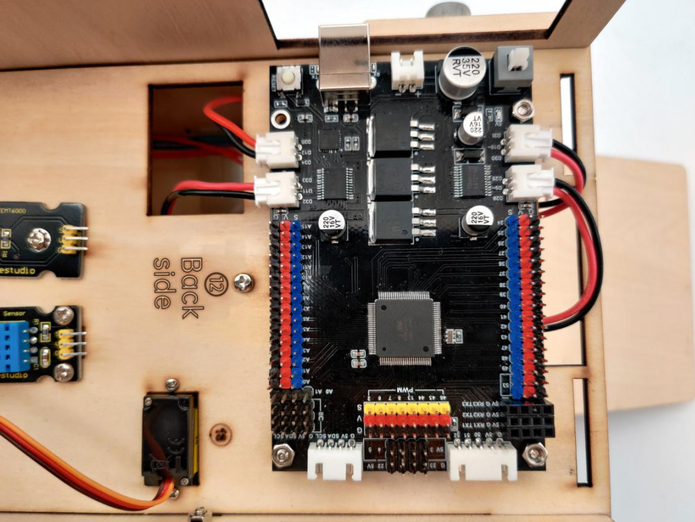
-1681697254551-356.jpg)
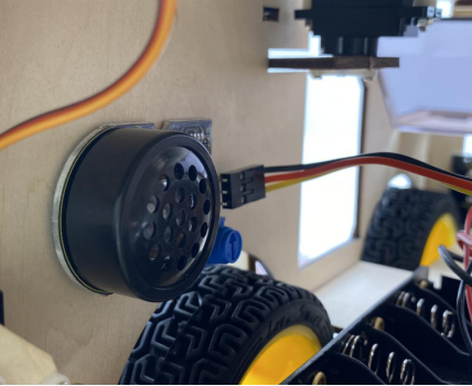
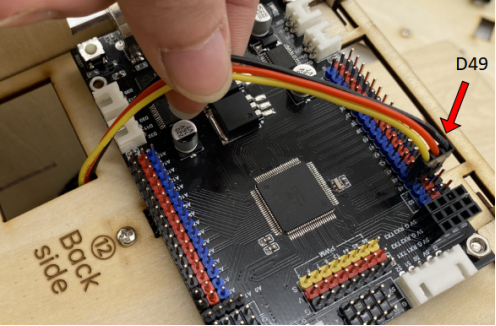
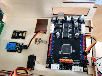
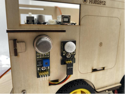


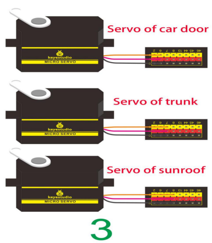
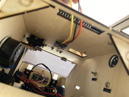
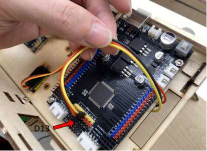
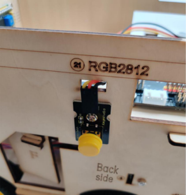
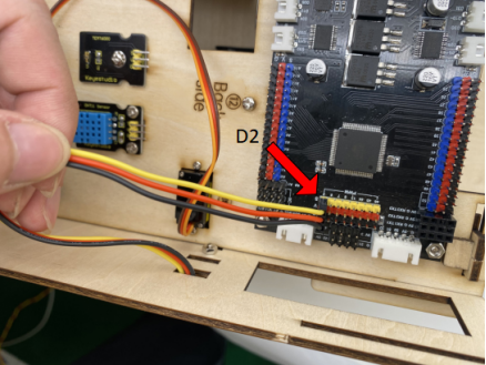
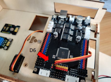
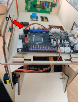
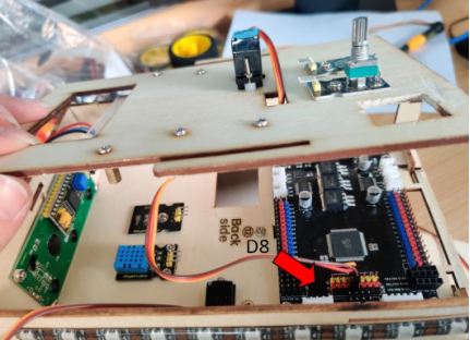

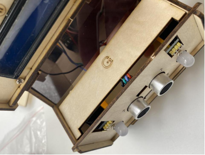
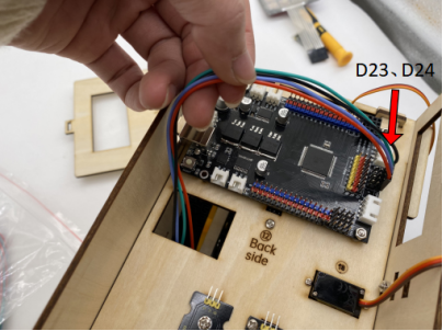
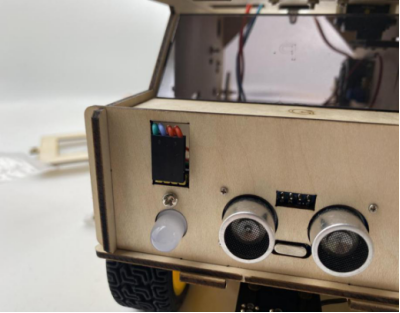
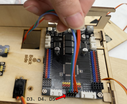
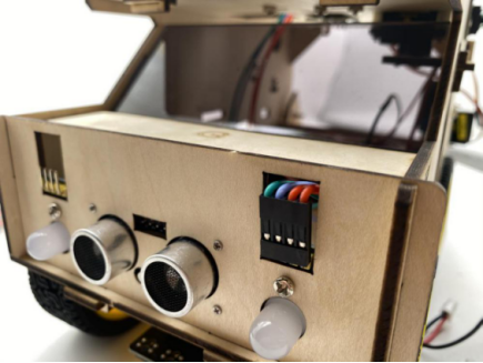
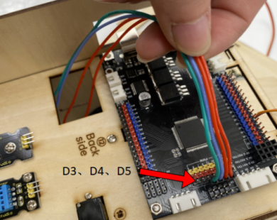

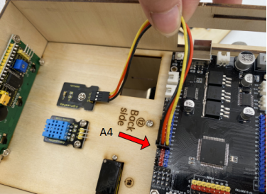
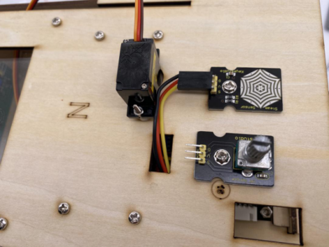
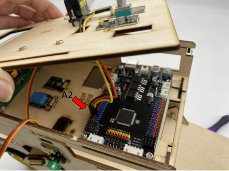
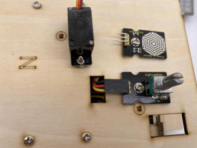
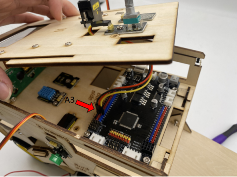
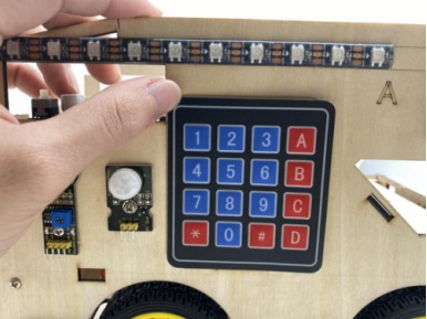
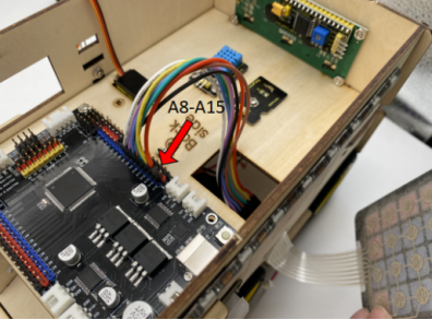

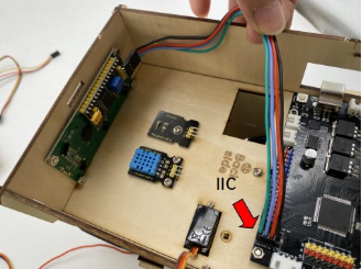
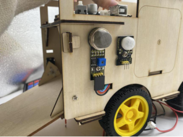
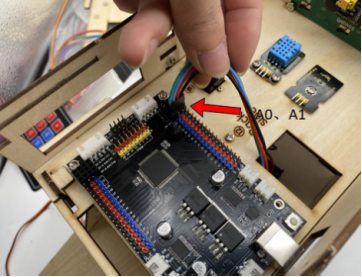

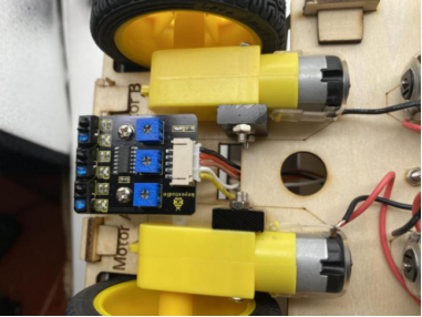
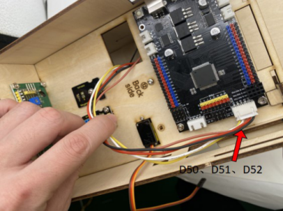
Note: be careful to mount board because its protruding part is weak.
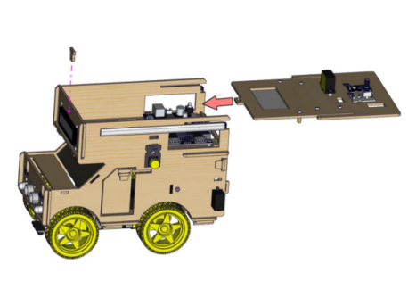
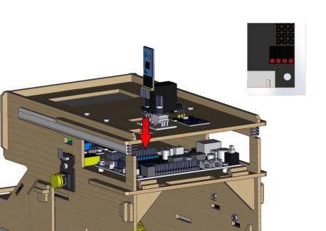
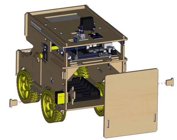
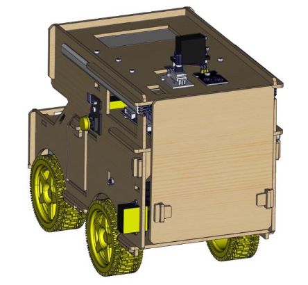
Project 21: Line Tracking Motorhome
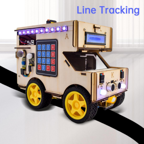
1.Description:
We’ve introduced how to work with sensors and modules. In this part, we will integrate some modules to finish more complex program. Next, we will make a line tracking smart motorhome.
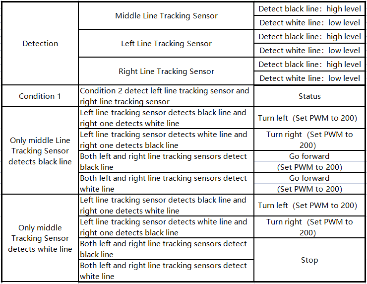
2.Flow Chart
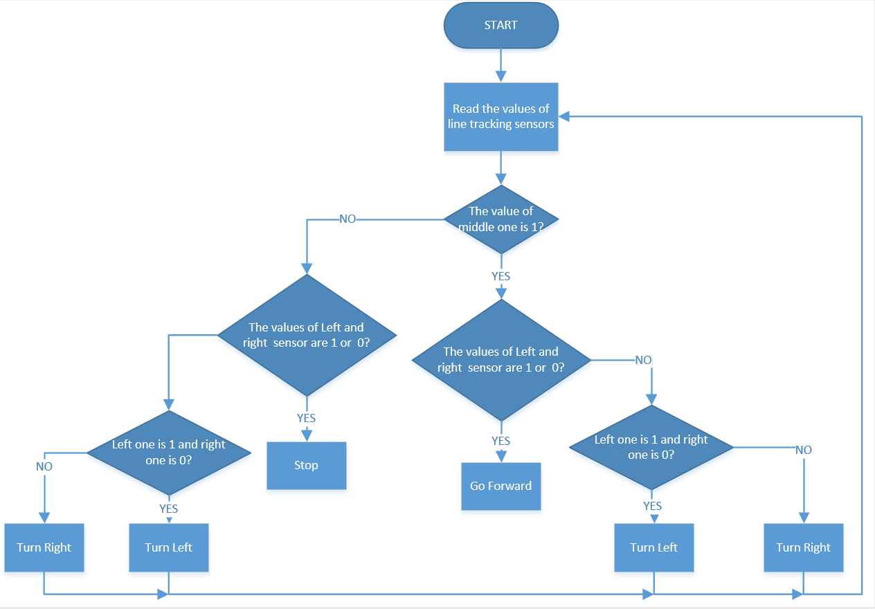
3.Connection Diagram
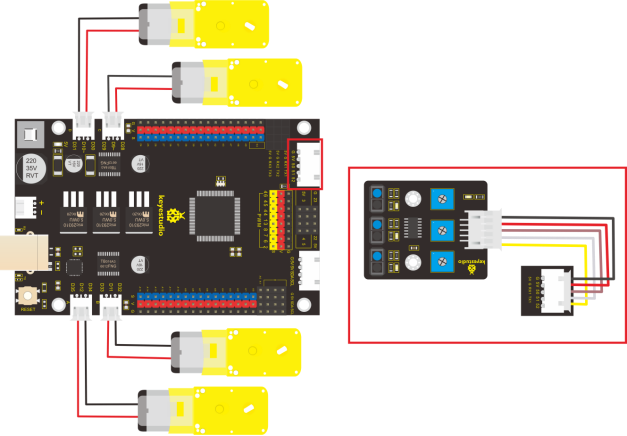
4.Test Code
/*
  keyestudio smart motorhome
  lesson 21
  Tracking motorhome
  http://www.keyestudio.com
*/
//Line Tracking Sensor
#define L_pin  50
#define M_pin  51
#define R_pin  52

//define the pins of motor A, B, C and D
const int MA1 = 35;
const int MA2 = 34;
const int PWMA = 12;

const int MB1 = 33;
const int MB2 = 32;
const int PWMB = 11;

const int MC1 = 29;
const int MC2 = 28;
const int PWMC = 9;

const int MD1 = 31;
const int MD2 = 30;
const int PWMD = 10;

volatile int speeds = 120;  //define the speed variable speeds
void setup() {
  pinMode(L_pin, INPUT); //set the pins of line tracking sensor to INPUT
  pinMode(M_pin, INPUT);
  pinMode(R_pin, INPUT);

  //set ports of motor to OUTPUT
  pinMode(MA1, OUTPUT);
  pinMode(MA2, OUTPUT);

  pinMode(MB1, OUTPUT);
  pinMode(MB2, OUTPUT);

  pinMode(MC1, OUTPUT);
  pinMode(MC2, OUTPUT);

  pinMode(MD1, OUTPUT);
  pinMode(MD2, OUTPUT);
}

void loop () {
  int L_val = digitalRead(L_pin); //read the value of left sensor
  int M_val = digitalRead(M_pin); //read the value of middle sensor
  int R_val = digitalRead(R_pin); //read the value of right sensor
  if (M_val == 1) { //the middle one detects black line
    if (L_val == 1 && R_val == 0) { //if only left sensor detects black line, turn left
      turnleft();
    }
    else if (L_val == 0 && R_val == 1) { //if only right sensor detects black line, turn right
      turnright();
    }
    else { //go forward
      advance();
    }
  }
  else { //the middle sensor detects black line
    if (L_val == 1 && R_val == 0) { //if only left sensor detects black line, turn left
      turnleft();
    }
    else if (L_val == 0 && R_val == 1) { //if only right sensor detects black line,turn right
    }
    else { //stop
      Stop();
    }
  }

}

void advance() {    //go forward
  //Motor A rotates clockwise
  digitalWrite(MA1, HIGH);
  digitalWrite(MA2, LOW);
  analogWrite(PWMA, speeds);
  //Motor B rotates clockwise
  digitalWrite(MB1, LOW);
  digitalWrite(MB2, HIGH);
  analogWrite(PWMB, speeds);
  //Motor C rotates clockwise
  digitalWrite(MC1, LOW);
  digitalWrite(MC2, HIGH);
  analogWrite(PWMC, speeds);
  //Motor D rotates clockwise
  digitalWrite(MD1, HIGH);
  digitalWrite(MD2, LOW);
  analogWrite(PWMD, speeds);
}

void back() {   //go back
  //Motor A rotates anticlockwise
  digitalWrite(MA1, LOW);
  digitalWrite(MA2, HIGH);
  analogWrite(PWMA, speeds);
  //Motor B rotates anticlockwise
  digitalWrite(MB1, HIGH);
  digitalWrite(MB2, LOW);
  analogWrite(PWMB, speeds);
  //Motor C rotates anticlockwise
  digitalWrite(MC1, HIGH);
  digitalWrite(MC2, LOW);
  analogWrite(PWMC, speeds);
  //Motor D rotates anticlockwise
  digitalWrite(MD1, LOW);
  digitalWrite(MD2, HIGH);
  analogWrite(PWMD, speeds);
}

void turnleft() {   //turn left
  //Motor A rotates clockwise
  digitalWrite(MA1, HIGH);
  digitalWrite(MA2, LOW);
  analogWrite(PWMA, speeds);
  //Motor B rotates anticlockwise
  digitalWrite(MB1, HIGH);
  digitalWrite(MB2, LOW);
  analogWrite(PWMB, speeds);
  //Motor C rotates anticlockwise
  digitalWrite(MC1, HIGH);
  digitalWrite(MC2, LOW);
  analogWrite(PWMC, speeds);
  //Motor D rotates clockwise
  digitalWrite(MD1, HIGH);
  digitalWrite(MD2, LOW);
  analogWrite(PWMD, speeds);
}

void turnright() {    //turn right
  //Motor A rotates anticlockwise
  digitalWrite(MA1, LOW);
  digitalWrite(MA2, HIGH);
  analogWrite(PWMA, speeds);
  //Motor B rotates clockwise
  digitalWrite(MB1, LOW);
  digitalWrite(MB2, HIGH);
  analogWrite(PWMB, speeds);
  //Motor C rotates clockwise
  digitalWrite(MC1, LOW);
  digitalWrite(MC2, HIGH);
  analogWrite(PWMC, speeds);
  //Motor D rotates anticlockwise
  digitalWrite(MD1, LOW);
  digitalWrite(MD2, HIGH);
  analogWrite(PWMD, speeds);
}

void Stop() {   //stop
  //set the speed of four motors to 0
  analogWrite(PWMA, 0);
  analogWrite(PWMB, 0);
  analogWrite(PWMC, 0);
  analogWrite(PWMD, 0);
}
5.Test Result
Upload code to development board and power on. The smart motorhome runs along black tracks. However, if it deviates from the track, the RV can automatically adjust back.
Project 22: Ultrasonic Follow Motorhome
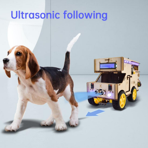
1.Description:
In this lesson, we will make an ultrasonic follow motorhome based on the working principle of ultrasonic sensor. The ultrasonic sensor detects the distance between obstacle and car. Then we will drive motorhome to move through the distance value.
Detection: Ultrasonic Ranging(distance(cm))
Condition |
Status |
|---|---|
distance<=8 |
Go back(set PWM to 120) |
8<distance<=15 |
Stop |
15<distance<35 |
Go forward(set PWM to 120) |
distance>35 |
Stop |
2.Flow Chart
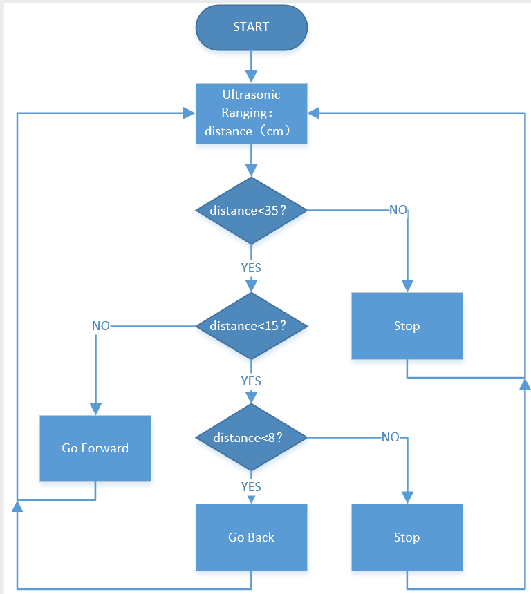
3.Connection Diagram

4.Test Code
/*
  keyestudio smart motorhome
  lesson 22
  flowing motorhome
  http://www.keyestudio.com
*/
//Ultrasonic Sensor
#define EchoPin  23  //ECHO to D23
#define TrigPin  22  //TRIG to D22

//define the pins of motor A, B, C and D
const int MA1 = 35;
const int MA2 = 34;
const int PWMA = 12;

const int MB1 = 33;
const int MB2 = 32;
const int PWMB = 11;

const int MC1 = 29;
const int MC2 = 28;
const int PWMC = 9;

const int MD1 = 31;
const int MD2 = 30;
const int PWMD = 10;

volatile int speeds = 120;  //define the speed variable speeds
volatile int distance;
void setup() {
  pinMode(EchoPin, INPUT);  //set pin ECHO to INPUT
  pinMode(TrigPin, OUTPUT);  //set pin TRIG to OUTPUT
  //set the ports of motor to OUTPUT
  pinMode(MA1, OUTPUT);
  pinMode(MA2, OUTPUT);

  pinMode(MB1, OUTPUT);
  pinMode(MB2, OUTPUT);

  pinMode(MC1, OUTPUT);
  pinMode(MC2, OUTPUT);

  pinMode(MD1, OUTPUT);
  pinMode(MD2, OUTPUT);
}

void loop () {
  distance = get_distance();
  if (distance <= 8) {
    back();
  }
  else if (distance > 8 && distance <= 15) {
    Stop();
  }
  else if (distance > 15 && distance <= 35) {
    advance();
  }
  else {
    Stop();
  }

}

int get_distance() {  //detect distance by ultrasonic sensor
  int dis;
  digitalWrite(TrigPin, LOW);
  delayMicroseconds(2);
  digitalWrite(TrigPin, HIGH);  //trigger at least 10us high level to TRIG
  delayMicroseconds(10);
  digitalWrite(TrigPin, LOW);
  dis = pulseIn(EchoPin, HIGH) / 58;  //calculate the distance
  delay(10);
  return dis;
}

void advance() {    //go forward
  //Motor A rotates clockwise
  digitalWrite(MA1, HIGH);
  digitalWrite(MA2, LOW);
  analogWrite(PWMA, speeds);
  //Motor B rotates clockwise
  digitalWrite(MB1, LOW);
  digitalWrite(MB2, HIGH);
  analogWrite(PWMB, speeds);
  //Motor C rotates clockwise
  digitalWrite(MC1, LOW);
  digitalWrite(MC2, HIGH);
  analogWrite(PWMC, speeds);
  //Motor D rotates clockwise
  digitalWrite(MD1, HIGH);
  digitalWrite(MD2, LOW);
  analogWrite(PWMD, speeds);
}

void back() {   //go back
  //Motor A rotates anticlockwise
  digitalWrite(MA1, LOW);
  digitalWrite(MA2, HIGH);
  analogWrite(PWMA, speeds);
  //Motor B rotates anticlockwise
  digitalWrite(MB1, HIGH);
  digitalWrite(MB2, LOW);
  analogWrite(PWMB, speeds);
  //Motor C rotates anticlockwise
  digitalWrite(MC1, HIGH);
  digitalWrite(MC2, LOW);
  analogWrite(PWMC, speeds);
  //Motor D rotates anticlockwise
  digitalWrite(MD1, LOW);
  digitalWrite(MD2, HIGH);
  analogWrite(PWMD, speeds);
}

void turnleft() {   //turn left
  //Motor A rotates clockwise
  digitalWrite(MA1, HIGH);
  digitalWrite(MA2, LOW);
  analogWrite(PWMA, speeds);
  //Motor B rotates anticlockwise
  digitalWrite(MB1, HIGH);
  digitalWrite(MB2, LOW);
  analogWrite(PWMB, speeds);
  //Motor C rotates anticlockwise
  digitalWrite(MC1, HIGH);
  digitalWrite(MC2, LOW);
  analogWrite(PWMC, speeds);
  //Motor D rotates clockwise
  digitalWrite(MD1, HIGH);
  digitalWrite(MD2, LOW);
  analogWrite(PWMD, speeds);
}

void turnright() {    //turn right
  //Motor A rotates anticlockwise
  digitalWrite(MA1, LOW);
  digitalWrite(MA2, HIGH);
  analogWrite(PWMA, speeds);
  //Motor B rotates clockwise
  digitalWrite(MB1, LOW);
  digitalWrite(MB2, HIGH);
  analogWrite(PWMB, speeds);
  //Motor C rotates clockwise
  digitalWrite(MC1, LOW);
  digitalWrite(MC2, HIGH);
  analogWrite(PWMC, speeds);
  //Motor D rotates anticlockwise
  digitalWrite(MD1, LOW);
  digitalWrite(MD2, HIGH);
  analogWrite(PWMD, speeds);
}

void Stop() {   //stop
  //set the speed of four motors to 0
  analogWrite(PWMA, 0);
  analogWrite(PWMB, 0);
  analogWrite(PWMC, 0);
  analogWrite(PWMD, 0);
}
5.Test Result
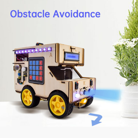
Upload code to development board and wire up according to connection diagram. The smart motorhome will follow the obstacle to move.
Project 23: Ultrasonic Obstacle Avoidance Motorhome
1.Description:
In previous lesson, we made a follow smart motorhome. Equally, we can transform it into ultrasonic obstacle avoidance motorhome through code. Let’s get started.
Detection: Ultrasonic Ranging (distance(cm))
Condition |
Status |
|
|---|---|---|
distance<8 |
Go back for 300ms |
|
distance<15 |
Turn left for 300ms |
|
distance>=15 |
Go forward |
2.Flow Chart
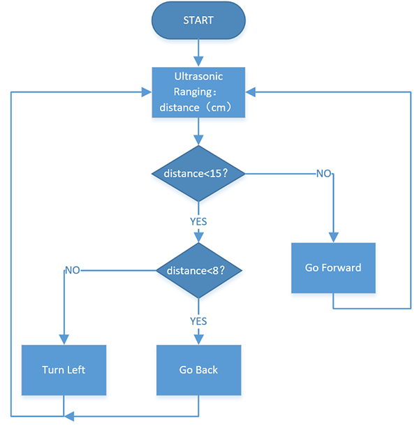
3.Connection Diagram

4.Test Code
/*
  keyestudio smart motorhome
  lesson 23
  avoiding motorhome  http://www.keyestudio.com
*/
//Ultrasonic Sensor
#define EchoPin  23  //ECHO to D23
#define TrigPin  22  //TRIG to D22

//define the pins of motor A, B, C and D
const int MA1 = 35;
const int MA2 = 34;
const int PWMA = 12;

const int MB1 = 33;
const int MB2 = 32;
const int PWMB = 11;

const int MC1 = 29;
const int MC2 = 28;
const int PWMC = 9;

const int MD1 = 31;
const int MD2 = 30;
const int PWMD = 10;

volatile int speeds = 120;  //define the speed variable speeds
volatile int distance;
void setup() {
  pinMode(EchoPin, INPUT);  //set pin ECHO to INPUT
  pinMode(TrigPin, OUTPUT);  //set pin TRIG to OUTPUT

  //set the ports of motor to OUTPUT
  pinMode(MA1, OUTPUT);
  pinMode(MA2, OUTPUT);

  pinMode(MB1, OUTPUT);
  pinMode(MB2, OUTPUT);

  pinMode(MC1, OUTPUT);
  pinMode(MC2, OUTPUT);

  pinMode(MD1, OUTPUT);
  pinMode(MD2, OUTPUT);
}

void loop () {
  distance = get_distance();  //set the distance to variable distance
  if (distance < 8) {
    back();
    delay(300);
  }
  else if (distance < 15) {
    turnleft();
    delay(300);
  }
  else {
    advance();
  }

}

int get_distance() {  //detect distance by ultrasonic sensor
  int dis;
  digitalWrite(TrigPin, LOW);
  delayMicroseconds(2);
  digitalWrite(TrigPin, HIGH);  //trigger at least 10us high level to TRIG
  delayMicroseconds(10);
  digitalWrite(TrigPin, LOW);
  dis = pulseIn(EchoPin, HIGH) / 58;  //计calculate the distance
  delay(10);
  return dis;
}

void advance() {    //go forward
  //Motor A rotates clockwise
  digitalWrite(MA1, HIGH);
  digitalWrite(MA2, LOW);
  analogWrite(PWMA, speeds);
  //Motor B rotates clockwise
  digitalWrite(MB1, LOW);
  digitalWrite(MB2, HIGH);
  analogWrite(PWMB, speeds);
  //Motor C rotates clockwise
  digitalWrite(MC1, LOW);
  digitalWrite(MC2, HIGH);
  analogWrite(PWMC, speeds);
  //Motor D rotates clockwise
  digitalWrite(MD1, HIGH);
  digitalWrite(MD2, LOW);
  analogWrite(PWMD, speeds);
}

void back() {   //go back
  //Motor A rotates anticlockwise
  digitalWrite(MA1, LOW);
  digitalWrite(MA2, HIGH);
  analogWrite(PWMA, speeds);
  //Motor B rotates anticlockwise
  digitalWrite(MB1, HIGH);
  digitalWrite(MB2, LOW);
  analogWrite(PWMB, speeds);
  //Motor C rotates anticlockwise
  digitalWrite(MC1, HIGH);
  digitalWrite(MC2, LOW);
  analogWrite(PWMC, speeds);
  //Motor D rotates anticlockwise
  digitalWrite(MD1, LOW);
  digitalWrite(MD2, HIGH);
  analogWrite(PWMD, speeds);
}

void turnleft() {   //turn left
  //Motor A rotates clockwise
  digitalWrite(MA1, HIGH);
  digitalWrite(MA2, LOW);
  analogWrite(PWMA, speeds);
  //Motor B rotates anticlockwise
  digitalWrite(MB1, HIGH);
  digitalWrite(MB2, LOW);
  analogWrite(PWMB, speeds);
  //Motor C rotates anticlockwise
  digitalWrite(MC1, HIGH);
  digitalWrite(MC2, LOW);
  analogWrite(PWMC, speeds);
  //Motor D rotates clockwise
  digitalWrite(MD1, HIGH);
  digitalWrite(MD2, LOW);
  analogWrite(PWMD, speeds);
}

void turnright() {    //turn right
  //Motor A rotates anticlockwise
  digitalWrite(MA1, LOW);
  digitalWrite(MA2, HIGH);
  analogWrite(PWMA, speeds);
  //Motor B rotates clockwise
  digitalWrite(MB1, LOW);
  digitalWrite(MB2, HIGH);
  analogWrite(PWMB, speeds);
  //Motor C rotates clockwise
  digitalWrite(MC1, LOW);
  digitalWrite(MC2, HIGH);
  analogWrite(PWMC, speeds);
  //Motor D rotates anticlockwise
  digitalWrite(MD1, LOW);
  digitalWrite(MD2, HIGH);
  analogWrite(PWMD, speeds);
}

void Stop() {   //stop
  //set the speed of four motors to
  analogWrite(PWMA, 0);
  analogWrite(PWMB, 0);
  analogWrite(PWMC, 0);
  analogWrite(PWMD, 0);
}
5.Test Result
Upload code successfully, power on and smart motorhome goes forward. It can avoid the obstacle when meeting obstacle
Project 24: Bluetooth Control motorhome
1.Description:
We’ve learned the basic knowledge of Bluetooth, in this lesson, we will make a Bluetooth smart motorhome. In the experiment, we default the HM-10 Bluetooth module as a Slave and the cellphone as a Host.
Then install an App and connect to HM-10 Bluetooth module so as to control smart motorhome. Next, let’s control it through the key value of App.
Note: pin RXD1, TXD1, GND and VCC of Bluetooth module are interfaced with pin TX1, RX1, -(GND)and +(VCC)of mega2560 control board. Pin STATE and BRK don’t need connecting and BAT is connected to power.
The corresponding key values are shown below:
ICON |
FUNCTION |
|
|---|---|---|
|
Connect to HM-10 Bluetooth Module |
|
|
Disconnect Bluetooth |
|
|
Press to send“F” |
Go Forward; Stop |
|
Press to send“L” |
Turn Left; Stop |
|
Press to send“R” |
Turn Right; Stop |
|
Press to send“B” |
Go Back; Stop |


2.Flow Chart:
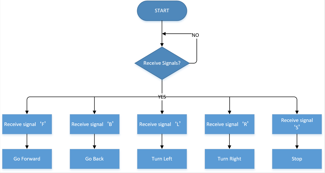
3.Connection Diagram

4.Test Code
/*
  keyestudio smart RV
  lesson 24.1
  blutooth control RV
  http://www.keyestudio.com
*/

//define the pins of motor A, B, C and D
const int MA1 = 35;
const int MA2 = 34;
const int PWMA = 12;

const int MB1 = 33;
const int MB2 = 32;
const int PWMB = 11;

const int MC1 = 29;
const int MC2 = 28;
const int PWMC = 9;

const int MD1 = 31;
const int MD2 = 30;
const int PWMD = 10;

volatile int speeds = 120;  //define the speed variable speeds
char ble_val;   //set variable ble_val
void setup() {
  Serial1.begin(9600);  //set Bluetooth baud rate to 9600
  //set the ports of motor to OUTPUT
  pinMode(MA1, OUTPUT);
  pinMode(MA2, OUTPUT);

  pinMode(MB1, OUTPUT);
  pinMode(MB2, OUTPUT);

  pinMode(MC1, OUTPUT);
  pinMode(MC2, OUTPUT);

  pinMode(MD1, OUTPUT);
  pinMode(MD2, OUTPUT);
}

void loop () {
  if (Serial1.available() > 0) //serial port reads characters
  {
    ble_val = Serial1.read();//set the character read by serial port to val
    switch (ble_val)
    {
      case 'F':  advance();    break;
      case 'B':  back();       break;
      case 'L':  turnleft();   break;
      case 'R':  turnright();  break;
      case 'S':  Stop();       break;
    }
  }

}

void advance() {    //go forward
  //Motor A rotates clockwise
  digitalWrite(MA1, HIGH);
  digitalWrite(MA2, LOW);
  analogWrite(PWMA, speeds);
  //Motor B rotates clockwise
  digitalWrite(MB1, LOW);
  digitalWrite(MB2, HIGH);
  analogWrite(PWMB, speeds);
  //Motor C rotates clockwise
  digitalWrite(MC1, LOW);
  digitalWrite(MC2, HIGH);
  analogWrite(PWMC, speeds);
  //Motor D rotates clockwise
  digitalWrite(MD1, HIGH);
  digitalWrite(MD2, LOW);
  analogWrite(PWMD, speeds);
}

void back() {   //go back
  //Motor A rotates anticlockwise
  digitalWrite(MA1, LOW);
  digitalWrite(MA2, HIGH);
  analogWrite(PWMA, speeds);
  //Motor B rotates anticlockwise
  digitalWrite(MB1, HIGH);
  digitalWrite(MB2, LOW);
  analogWrite(PWMB, speeds);
  //Motor C rotates anticlockwise
  digitalWrite(MC1, HIGH);
  digitalWrite(MC2, LOW);
  analogWrite(PWMC, speeds);
  //Motor D rotates anticlockwise
  digitalWrite(MD1, LOW);
  digitalWrite(MD2, HIGH);
  analogWrite(PWMD, speeds);
}

void turnleft() {   //turn left
  //Motor A rotates clockwise
  digitalWrite(MA1, HIGH);
  digitalWrite(MA2, LOW);
  analogWrite(PWMA, speeds);
  //Motor B rotates anticlockwise
  digitalWrite(MB1, HIGH);
  digitalWrite(MB2, LOW);
  analogWrite(PWMB, speeds);
  //Motor C rotates anticlockwise
  digitalWrite(MC1, HIGH);
  digitalWrite(MC2, LOW);
  analogWrite(PWMC, speeds);
  //Motor D rotates clockwise
  digitalWrite(MD1, HIGH);
  digitalWrite(MD2, LOW);
  analogWrite(PWMD, speeds);
}

void turnright() {    //turn right
  //Motor A rotates anticlockwise
  digitalWrite(MA1, LOW);
  digitalWrite(MA2, HIGH);
  analogWrite(PWMA, speeds);
  //Motor B rotates clockwise
  digitalWrite(MB1, LOW);
  digitalWrite(MB2, HIGH);
  analogWrite(PWMB, speeds);
  //Motor C rotates clockwise
  digitalWrite(MC1, LOW);
  digitalWrite(MC2, HIGH);
  analogWrite(PWMC, speeds);
  //Motor D rotates anticlockwise
  digitalWrite(MD1, LOW);
  digitalWrite(MD2, HIGH);
  analogWrite(PWMD, speeds);
}

void Stop() {   //stop
  //set the speed of four motors to 0
  analogWrite(PWMA, 0);
  analogWrite(PWMB, 0);
  analogWrite(PWMC, 0);
  analogWrite(PWMD, 0);
}
Upload code, power on and connect to App. The speed is increasing to 255 when the speed-up button is pressed, however, speed is reducing to 0 when the speed-down button is pressed. As shown below:
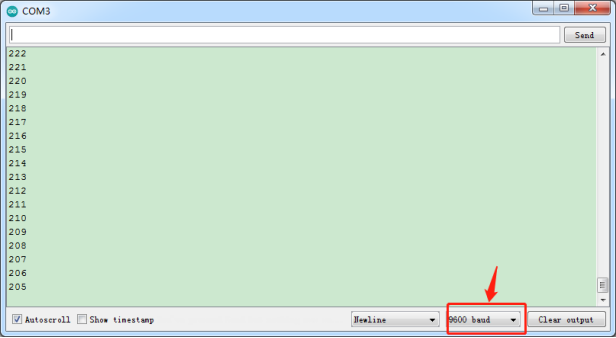
Project 25: Multi-purpose Smart Motorhome
1.Description:
In this chapter, we will test the function of smart motorhome via App. And we combine all functions together to make motorhome perform them.
Next we will make a comprehensive flow chart, test the wiring-up and upload code to make a multi-purpose smart motorhome.
ICON |
FUNCTION |
|
|---|---|---|
|
Pair HM-10 Bluetooth module |
|
|
Disconnect Bluetooth |
|
|
Press icon to send character“F” |
Go Forward |
|
Press icon to send character“L”; |
urn Left |
|
Press icon to send character“R”; |
Turn Right |
|
Press icon to send character“B”; |
Go Back |
|
Press icon to send character“Z”; |
Speed up; |
|
Press it to send character“X”; |
Speed down; |
|
Press it to send character“h”; |
Activate the obstacle avoidance mode; |
|
Press icon to send character“i”; |
Activate follow mode; |
|
Press icon to send character“j”; |
Activate line tracking mode; |
|
Press icon to send character“a”; |
Show red color |
|
Press icon to send character“b” |
Show orange color |
|
Press icon to send character“c” |
Show yellow color |
|
Press icon to send character“d” |
Show green color |
|
Press icon to send character“e” |
Show cyan color |
|
Press icon to send character“f” |
Show blue color |
|
Press icon to send character“g” |
Show purple color |
|
Press icon to send character“o” |
Switch to next color |
|
Press icon to send character“p” |
Switch to the previous color |
|
Press icon to send character“q” |
Turn off 2812 light strip |
|
Press icon to send character“1”; |
Emit sound“do” |
|
Press icon to send character“2”; |
Emit sound “re”; |
|
Press icon to send character“3”; |
Emit sound“mi” ; |
|
Press icon to send character“4”; |
Emit sound“fa””; |
|
Press icon to send character“5”; |
Emit sound “so”; |
|
Press icon to send character“6”; |
Emit sound“la”; |
|
Press icon to send character“7”; |
Emit sound“si”; |
|
Press icon to send character“A”; |
Turn on LED |
|
Press icon to send character“m”; |
Turn on 2812 light, |
|
Press icon to send character“J”; |
Play music |
|
Press icon to send character“w”; |
Check humidity |
|
Press icon to send character“l”; |
Check temperature |
|
Press icon to send character“t”; |
Check steam value |
|
Press icon to send character“k”; |
Check gas concentration |
|
Press icon to send character“y”; |
Check the brightness |
|
Press icon to send character“*”; |
Check if there is someone |
|
Press icon to send character“W”; |
Open and close car door |
|
Press icon to send character“U”; |
Open and close roof window |
|
Press icon to send character“P”; |
Open and close trunk |
|
Press icon to send character“V”; |
Display and turn off red color |
|
Press icon to send character“n”; |
Display and turn off green color |
|
Press icon to send character“Q”; |
Display and turn off blue color |


2.Connection Diagram
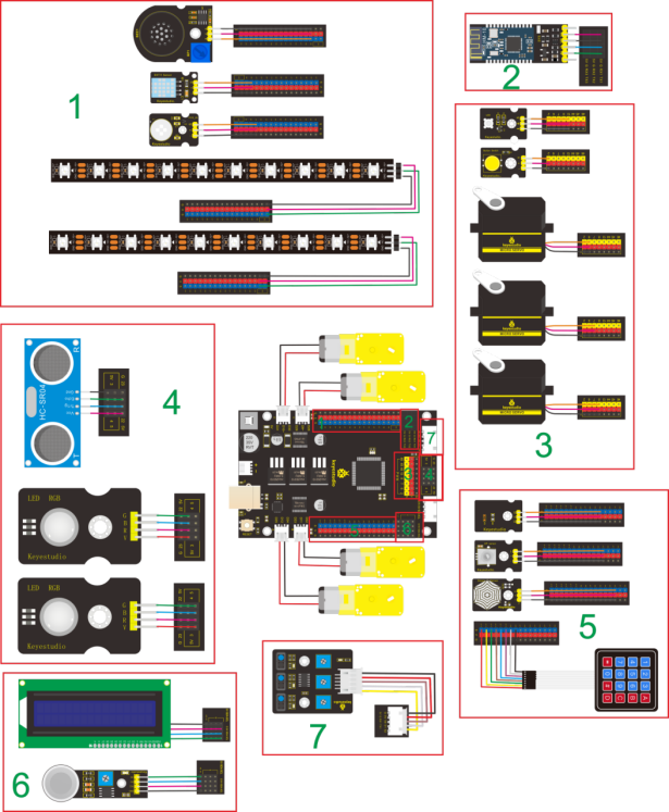
3.Test Code
/*
keyestudio smart motorhome
lesson 25
Smart Motorhome
http://www.keyestudio.com
*/
#include <Adafruit_NeoPixel.h>
Adafruit_NeoPixel rgb_2812 = Adafruit_NeoPixel(10, 53, NEO_GRB + NEO_KHZ800);
const int door_servo = 6; //connect servo of door to D6
const int trunk_servo = 7; //connect servo of sunroof to D7
const int skylight_servo = 8; //connect the servo of trunk to D8
#include <dht11.h> //include the library code:
dht11 DHT;
#define DHT11_PIN 48 //define DHT11 as digital 48
#include <Wire.h>
#include <LiquidCrystal_I2C.h> // includes the LiquidCrystal_I2C Library
LiquidCrystal_I2C lcd(0x27, 16, 2); // set the LCD addrecount to 0x27 for a 16 chars and 2 line display
#include <Keypad.h>
const byte ROWS = 4; //four rows
const byte COLS = 4; //four columns
char keyprecounted; //used to receive the key value
//define the cymbols on the buttons of the keypads
char keyMap[ROWS][COLS] = { //define the key value of keyboard
{'1', '2', '3', 'A'},
{'4', '5', '6', 'B'},
{'7', '8', '9', 'C'},
{'*', '0', '#', 'D'}
};
byte rowPins[ROWS] = {A8, A9, A10, A11}; //Row pinouts of the keypad
byte colPins[COLS] = {A12, A13, A14, A15}; //Column pinouts of the keypad
Keypad myKeypad = Keypad( makeKeymap(keyMap), rowPins, colPins, ROWS, COLS);
//wire up ultrasonic sensor
#define EchoPin 23 //ECHO to D23
#define TrigPin 22 //TRIG to D22
#define buzzer 49 //buzzer pin to D49
#define RES A3 //potentiometer pin to A3
#define photos A4 //photoresistance pin to A4
#define PIR 47 //PIR pin to 47
#define MQ2_A A0
#define MQ2_D A1 //treat analog ports as digital ports
#define waterpin A2
//wire up line tracking sensor
#define L_pin 50
#define M_pin 51
#define R_pin 52
#define LED 13 //led pin to D13
#define button 2 //button pin to D2
#define RGB_R 3 //connect RGB_R to D3
#define RGB_B 4 //interface RGB_B with D4
#define RGB_G 5 //interface RGB_G with D5
//define the pins of motor A, B, C and D
const int MA1 = 35;
const int MA2 = 34;
const int PWMA = 12;
const int MB1 = 33;
const int MB2 = 32;
const int PWMB = 11;
const int MC1 = 28;
const int MC2 = 29;
const int PWMC = 9;
const int MD1 = 30;
const int MD2 = 31;
const int PWMD = 10;
volatile int speeds = 150; //define the speed variable speeds
volatile int distance;
String password1 = "0000"; //define the four bits initial password of door
String password2 = "1111"; //define the four bits initial password of trunk
String tempPassword = "";
int k = 5;
String servo_door; //set variable string servo_door
volatile int servo_door_angle; //set variable servo_door_angle
String servo_trunk; //set variable string servo_trunk
volatile int servo_trunk_angle; //set variable servo_trunk_angle
String servo_skylight; //set variable string servo_trunk
volatile int servo_skylight_angle; //set variable servo_skylight_angle
String R; //set variable string R
volatile int value_R; //set variable value_R
String G; //set variable string G
volatile int value_G; //set variable value_G
String B; //set variable string B
volatile int value_B; //set variable value_B
char ble_val; //set variable ble_val
volatile int light; //set variable light
volatile int gas; //set variable gas
volatile int water; //set variable water
volatile int infrar; //set variable infrar
int color_num = 0;
int length;
#define D0 -1
#define D1 262
#define D2 293
#define D3 329
#define D4 349
#define D5 392
#define D6 440
#define D7 494
#define M1 523
#define M2 586
#define M3 658
#define M4 697
#define M5 783
#define M6 879
#define M7 987
#define H1 1045
#define H2 1171
#define H3 1316
#define H4 1393
#define H5 1563
#define H6 1755
#define H7 1971
//list out all D frequency
#define WHOLE 1
#define HALF 0.5
#define QUARTER 0.25
#define EIGHTH 0.25
#define SIXTEENTH 0.625
//list out all beats
int tune[] = //list out all frequency
{
M3, M3, M4, M5,
M5, M4, M3, M2,
M1, M1, M2, M3,
M3, M2, M2,
M3, M3, M4, M5,
M5, M4, M3, M2,
M1, M1, M2, M3,
M2, M1, M1,
M2, M2, M3, M1,
M2, M3, M4, M3, M1,
M2, M3, M4, M3, M2,
M1, M2, D5, D0,
M3, M3, M4, M5,
M5, M4, M3, M4, M2,
M1, M1, M2, M3,
M2, M1, M1
};
float durt[] = //list out all beats
{
1, 1, 1, 1,
1, 1, 1, 1,
1, 1, 1, 1,
1 + 0.5, 0.5, 1 + 1,
1, 1, 1, 1,
1, 1, 1, 1,
1, 1, 1, 1,
1 + 0.5, 0.5, 1 + 1,
1, 1, 1, 1,
1, 0.5, 0.5, 1, 1,
1, 0.5, 0.5, 1, 1,
1, 1, 1, 1,
1, 1, 1, 1,
1, 1, 1, 0.5, 0.5,
1, 1, 1, 1,
1 + 0.5, 0.5, 1 + 1,
};
void setup() {
Serial.begin(9600); //serial monitor
Serial1.begin(9600); //Bluetooth
rgb_2812.begin(); //Startrgb2818
rgb_2812.setBrightness(100); //initialize 100(0~255)
rgb_2812.show(); //set NeoPixels to "off" state
pinMode(door_servo, OUTPUT); //set the pin of servo of door to OUTPUT
pinMode(trunk_servo, OUTPUT); //set the pin of servo of trunk to OUTPUT
pinMode(skylight_servo, OUTPUT);//Set the pin of servo of sunproof to OUTPUT
pinMode(buzzer, OUTPUT); //Set buzzer as an output
pinMode(EchoPin, INPUT); //set pin ECHO to INPUT
pinMode(TrigPin, OUTPUT); //set pin TRIG to OUTPUT
//pinMode(MQ2_D, INPUT);
pinMode(button, INPUT);// initialize digital pin button as an input.
//attachInterrupt(digitalPinToInterrupt(button), Switch, FALLING); //external interrupt 0, falling edge triggers
pinMode(L_pin, INPUT); //set the pins of line tracking sensor to INPUT
pinMode(M_pin, INPUT);
pinMode(R_pin, INPUT);
pinMode(LED, OUTPUT); //LED pin as an OUTPUT
//set the ports of motor to OUTPUT
pinMode(MA1, OUTPUT);
pinMode(MA2, OUTPUT);
pinMode(MB1, OUTPUT);
pinMode(MB2, OUTPUT);
pinMode(MC1, OUTPUT);
pinMode(MC2, OUTPUT);
pinMode(MD1, OUTPUT);
pinMode(MD2, OUTPUT);
//initialize LCD1602
lcd.init();
lcd.backlight();
length = sizeof(tune) / sizeof(tune[0]); //calculate the length
// Print a mecountage to the LCD.
lcd.setCursor(0, 0);
lcd.print("Please enter: ");
lcd.setCursor(0, 1);
lcd.print("pass>");
servopulse(skylight_servo, 180); //open sunroof
}
void loop() {
auto_sensor(); //auto detection
if (Serial1.available() > 0) // serial reads the characters
{
ble_val = Serial1.read(); //set the character read by serial port to val
Serial.println(ble_val); //serial port display, used to modulate
pwm_control(); //PWM display
//for not looping the program
if (ble_val == 'o') { //receive 'o',switch color
color_num++;
showColor();
}
else if (ble_val == 'p') { //receive 'p',switch color
color_num--;
showColor();
}
else if (ble_val == 'q') {
closeColor(); //receive 'q',turn off 2812
}
}
switch (ble_val) {
case 'F' : advance(); break; //receive ‘F’, go forward
case 'B' : back(); break; //receive ‘B’, go back
case 'L' : turnleft(); break; //receive ‘L’, turn left
case 'R' : turnright(); break; //receive ‘R’, turn right
case 'S' : Stop(); break; //receive ‘S’, stop
case 'Z': speeds_a(); break; //receive ‘Z’, motor speeds up
case 'X': speeds_d(); break; //receive ‘X’, motor speeds down
case 'h' : avoid(); break; //receive ‘h’, enter the obstacle avoidance mode
case 'i' : follow(); break; //receive ‘i’, enter the following mode
case 'j' : track(); break; //receive ‘j’, enter the line tracking mode
case 'A': //if ble_val is 'A',loop program
digitalWrite(LED, HIGH); //set digital 13 to high level,LED on
break; //exit loop
case 'H': //if ble_val is 'H',loop program
digitalWrite(LED, LOW); //set digital 13 to low level,LED off
break; //exit loop
case 'm': //if ble_val is 'm',loop program
rainbow(10); //2812 shows rainbow color
break; //exit loop
case 'G': //if ble_val is 'G',loop program
closeColor(); //turn off rainbow color function
break; //exit loop
case 'J': //if ble_val is 'J',loop program
music(); //play music
break; //exit loop
case 'y': //if ble_val is 'y',loop program
Serial1.println(light); //wrap and output the value of variable light
break; //exit loop
case 'k': //if ble_val is 'k',loop program
Serial1.println(gas); //wrap and output the value of variable gas
break; //exit loop
case 't': //if ble_val is 't',loop program
Serial1.println(water); //wrap and output the value of variable water
break; //exit loop
case 'l': //if ble_val is 'l',loop program
Serial1.println(DHT.temperature); //wrap and output the value of variable soil
break; //exit loop
case 'w': //if ble_val is‘w’,loop program
Serial1.println(DHT.humidity); //wrap and output the value of variable soil
break; //exit loop
case 'W': //if ble_val is 'W',loop program
servopulse(door_servo, 10); //open the door
break; //exit loop
case 'M': //if ble_val is 'M',loop program
servopulse(door_servo, 86); //close the door
break; //exit loop
case 'U': //if ble_val is 'U',loop program
servopulse(skylight_servo, 180); //open sun roof
break; //exit loop
case '9': //if ble_val is '9',loop program
servopulse(skylight_servo, 0); //close sunroof
break; //exit loop
case 'P': //if ble_val is 'P',loop program
servopulse(trunk_servo, 120); //turn on trunk
break; //exit loop
case '8': //if ble_val is '8',loop program
servopulse(trunk_servo, 0); //turn off trunk
break; //exit loop
case '*': //if val is ‘w’,loop program
if (infrar == 1) {
Serial1.println("somebody!"); //linefeed “somebody!”
} else {
Serial1.println("nobody"); //linefeed and output “nobody”
}
break; //exit loop
case 'V': set_RGBColor(0, 255, 255); break; //receive 'V' and show red color
case 'n': set_RGBColor(255, 0, 255); break; //receive 'n' and show green color
case 'Q': set_RGBColor(255, 255, 0); break; //receive 'Q' and show blue color
case 'Y': set_RGBColor(255, 255, 255); break; //receive 'Y',turn off
case 'a': set_RGBColor(0, 255, 255); break; //receive 'a'and show red color
case 'b': set_RGBColor(0, 90, 255); break; //receive 'b' and show orange color
case 'c': set_RGBColor(0, 0, 255); break; //receive 'c' and show yellow color
case 'd': set_RGBColor(255, 0, 255); break; //receive 'd' and show green color
case 'e': set_RGBColor(255, 0, 0); break; //receive 'e' and show cyan color
case 'f': set_RGBColor(255, 255, 0); break; //receive 'f' and show blue color
case 'g': set_RGBColor(95, 223, 15); break; //receive 'g' and show purple color
case '1': tone(buzzer, D1); break; //receive '1' and emit DO
case '2': tone(buzzer, D2); break; //receive '2' and emit Re
case '3': tone(buzzer, D3); break; //receive '3' and emit Mi
case '4': tone(buzzer, D4); break; //receive '4' and emit Fa
case '5': tone(buzzer, D5); break; //receive '5' and emit So
case '6': tone(buzzer, D6); break; //receive '6' and emit La
case '7': tone(buzzer, D7); break; //receive '7' and emit Si
case '0': noTone(buzzer); break; //receive ‘0’ and stop emitting sound
default : break;
}
}
void auto_sensor() {
infrar = digitalRead(PIR); //set the digital value of digital port PIR to infrar
gas = analogRead(MQ2_A); //set the analog value of MQ2 port to gas
if (gas > 700) { //if variable gas is more than 700
set_RGBColor(0, 255, 255);
while (1)
{
Serial1.println("danger"); //linefeed and output "danger"
tone(buzzer, 440, 200);
delay(300);
tone(buzzer, 440, 200);
delay(500);
gas = analogRead(MQ2_A); //set the analog value of MQ2_A to gas
if (gas < 100) //if variable gas is less than 100
{
set_RGBColor(255, 255, 255);
break; //exit loop
}
}
}
light = analogRead(photos); //set the analog value of photos to light
if (light < 5 && ble_val != 'H')//if varible light is less than 5 and not turning off light by hand
{
digitalWrite(LED, HIGH); //turn on light
} else {
if (ble_val != 'A' ) { //not turning on light by hand
digitalWrite(LED, LOW); //turn off light
}
}
water = analogRead(waterpin); //set the analog vlaue of waterpin to variable water
if (water > 800) //if variable water is more than 800
{
set_RGBColor(255, 255, 0);
while (1)
//loop program
{
Serial1.println("rain"); //linefeed and output "rain"
servopulse(skylight_servo, 0); //close sunroof
water = analogRead(waterpin); //set the analog vlaue of waterpin to variable water
if (water < 30) //if variable water is less than 30
{
set_RGBColor(255, 255, 255);
break; //exit loop program
}
}
} /*else { //otherwise
if (ble_val != 'v' && ble_val != '9') //if val is not equivalent to 'v' or '9', which means not turning off by hand
{
servopulse(skylight_servo, 180); //open sunroof
}
}*/
int chk;
chk = DHT.read(DHT11_PIN); // READ DATA
switch (chk) {
case DHTLIB_OK:
break;
case DHTLIB_ERROR_CHECKSUM: //Check and error return
break;
case DHTLIB_ERROR_TIMEOUT: //timeout error return
break;
default:
break;
}
if (DHT.humidity > 90 || DHT.temperature > 30) //if temperature or humidity is too high
{
set_RGBColor(0, 255, 255);
while (1) //loop program
{
// READ DATA
chk = DHT.read(DHT11_PIN);
switch (chk) {
case DHTLIB_OK:
break;
case DHTLIB_ERROR_CHECKSUM: //Check and error return
break;
case DHTLIB_ERROR_TIMEOUT: //timeout error return
break;
default:
break;
}
if (DHT.temperature > 30) {
tone(buzzer, 2000, 100);
delay(200);
Serial1.println("hyperthermal!"); //linefeed and output "hyperthermal"
}
else if (DHT.humidity > 90) {
tone(buzzer, 2000, 100);
delay(200);
Serial1.println("High humidity!"); //linefeed and output "High humidity"
}
if (DHT.humidity <= 90 && DHT.temperature <= 30) //if temperature or humidity is less than or equalent to threshold
{
set_RGBColor(255, 255, 255);
break; //exit program loop
}
}
}
enter(); //run password subroutine
}
void enter() { //Input subprogram
keyprecounted = myKeypad.getKey(); //Obtain key value
if (keyprecounted != NO_KEY) { //if key value is a number
if (keyprecounted == '0' || keyprecounted == '1' || keyprecounted == '2' || keyprecounted == '3' ||
keyprecounted == '4' || keyprecounted == '5' || keyprecounted == '6' || keyprecounted == '7' ||
keyprecounted == '8' || keyprecounted == '9' ) {
tempPassword += keyprecounted; //save variable tempPassword
tone(buzzer, 1000, 100); //the sound of button
lcd.setCursor(k, 1);
lcd.print("*"); //hide password
k++; //display on next bit
}
}
if (k > 9) { //if k>9 and password exceeds four digits
tempPassword = ""; //clear cached password
k = 5; //initialize value k
lcd.setCursor(0, 1); //initialize display interface
lcd.print("pass> ");
}
if ( keyprecounted == '*') { //press * key
k = 5; //initialize value k
if ( tempPassword == password1 ) { //if password is correct
//LCD shows "open!" at the first character of the second row
lcd.setCursor(0, 1);
lcd.print("open! ");
servopulse(door_servo, 10); //open the door
tempPassword = ""; //clear cached password
delay(2000); //wait for 3s
lcd.setCursor(0, 1); //initialize display interface
lcd.print("pass> ");
}else if ( tempPassword == password2 ) { //if password is correct
//LCD shows "open!" at the first character of the second row
lcd.setCursor(0, 1);
lcd.print("open! ");
servopulse(trunk_servo, 120); //open trunk
tempPassword = ""; //clear cached password
delay(2000); //wait for 3s
lcd.setCursor(0, 1); //initialize display interface
lcd.print("pass> ");
}
else { //if password is wrong
lcd.setCursor(0, 1); //prompt error
lcd.print("Wrong! Try Again");
tempPassword = ""; //clear cached password
delay(2000); //wait for 2s
lcd.setCursor(0, 1); //initialize display interface
lcd.print("pass> ");
}
}
}
//PWM and angle control of servo
void pwm_control() {
switch (ble_val)
{
case 'u': //when ble_val is 'u', loop program
servo_door = Serial1.readStringUntil('#');
servo_door_angle = String(servo_door).toInt();
servopulse(door_servo, servo_door_angle); //set the servo of door to servo_door_angle
break; //exit loop
case 'v': //when ble_val is 'v', loop program
servo_skylight = Serial1.readStringUntil('#');
servo_skylight_angle = String(servo_skylight).toInt();
servopulse(skylight_servo, servo_skylight_angle); //set the servo angle of sunroof to servo_skylight_angle
break;//exit loop
case 's': //when ble_val is 's', loop program
servo_trunk = Serial1.readStringUntil('#');
servo_trunk_angle = String(servo_trunk).toInt();
servopulse(trunk_servo, servo_trunk_angle); //set the servo angle of trunk to servo_trunk_angle
break; //exit loop
case 'x': //when ble_val is 'x', loop program
R = Serial1.readStringUntil('#');
value_R = String(R).toInt();
value_R = map(value_R, 0, 255, 255, 0); //map the value_R
analogWrite(RGB_R, value_R); //set the PWM value of digital 3 to value_R
break; //exit loop
case 'D': //when ble_val is 'D', loop program
G = Serial1.readStringUntil('#');
value_G = String(G).toInt();
value_G = map(value_G, 0, 255, 255, 0); //map the value_G
analogWrite(RGB_G, value_G); //set the PWM value of digital 5 to value_G
break; //exit loop
case 'E': //when ble_val is 'E', loop program
B = Serial1.readStringUntil('#');
value_B = String(B).toInt();
value_B = map(value_B, 0, 255, 255, 0); //map the value_B
analogWrite(RGB_B, value_B); //set the PWM value of digital 4 to value_B
break; //exit loop
}
}
void servopulse(int pin, int myangle) { //pulse function
int pulsewidth = map(myangle, 0, 180, 500, 2500); //map the angel to pulsewidth
for (int i = 0; i < 5; i++) { //output pulse
digitalWrite(pin, HIGH); //set the level of servo port to HIGH
delayMicroseconds(pulsewidth); //Delay the tine of pulsewidth
digitalWrite(pin, LOW); //set the level of servo port to LOW
delay(20 - pulsewidth / 1000);
}
}
void music() //play the "Ode to Joy" song
{
for (int x = 0; x < length; x++)
{
tone(buzzer, tune[x]);
delay(400 * durt[x]);
noTone(buzzer);
ble_val = Serial1.read();
if (ble_val == 'I') { //receive‘J’ and exit loop,stop playing music
noTone(buzzer);
break;
}
}
}
void set_RGBColor(int red, int green, int blue) { //set the color of RGB module
analogWrite(RGB_R, red);
analogWrite(RGB_G, green);
analogWrite(RGB_B, blue);
}
int get_distance() { //ultrasonic ranging
int dis;
digitalWrite(TrigPin, LOW);
delayMicroseconds(2);
digitalWrite(TrigPin, HIGH); //send at least 10us high level to trigger
delayMicroseconds(10);
digitalWrite(TrigPin, LOW);
dis = pulseIn(EchoPin, HIGH) / 58; //calculate distance
delay(10);
return dis;
}
void follow() { //ultrasonic following
while (1) {
distance = get_distance();
Serial.println(distance);
if (distance <= 8) {
back();
}
else if (distance > 8 && distance <= 15) {
Stop();
}
else if (distance > 15 && distance <= 35) {
advance();
}
else {
Stop();
}
ble_val = Serial1.read();
if (ble_val == 'S') { //receive‘S’ and exit loop,car stops
Stop();
break;
}
}
}
void avoid() { //ultrasonic avoiding
while (1) {
distance = get_distance(); //set distance to variable distance
Serial.println(distance);
if (distance < 8) {
back();
delay(300);
}
else if (distance < 15) {
turnleft();
delay(300);
}
else {
advance();
}
ble_val = Serial1.read();
if (ble_val == 'S') { //receive ‘S’ and exit loop,car stops
Stop();
break;
}
}
}
void track() {
int L_val;
int M_val;
int R_val;
while (1) {
L_val = digitalRead(L_pin); //read the value of left sensor
M_val = digitalRead(M_pin); //read the value of middle sensor
R_val = digitalRead(R_pin); //read the value of right sensor
if (M_val == 1) { //the middle sensor detects black lines
if (L_val == 1 && R_val == 0) { //if only left sensor detects black lines, turn left
turnleft();
}
else if (L_val == 0 && R_val == 1) { //if only right sensor detects black lines, turn right
turnright();
}
else { //go forward
advance();
}
}
else { //the middle sensor doesn't detect black lines
if (L_val == 1 && R_val == 0) { //if only left sensor detects black lines, turn left
turnleft();
}
else if (L_val == 0 && R_val == 1) { //if only right sensor detects black lines, turn right
turnright();
}
else { //stop
Stop();
}
}
ble_val = Serial1.read();
if (ble_val == 'S') { //receive ‘S’ and exit loop,car stops
Stop();
break;
}
}
}
void advance() { //go forward
//Motor A rotates clockwise
digitalWrite(MA1, LOW);
digitalWrite(MA2, HIGH);
analogWrite(PWMA, speeds);
//Motor B rotates clockwise
digitalWrite(MB1, HIGH);
digitalWrite(MB2, LOW);
analogWrite(PWMB, speeds);
//Motor C rotates clockwise
digitalWrite(MC1, HIGH);
digitalWrite(MC2, LOW);
analogWrite(PWMC, speeds);
//Motor D rotates clockwise
digitalWrite(MD1, LOW);
digitalWrite(MD2, HIGH);
analogWrite(PWMD, speeds);
}
void back() { //go back
//Motor A rotates anticlockwise
digitalWrite(MA1, HIGH);
digitalWrite(MA2, LOW);
analogWrite(PWMA, speeds);
//Motor B rotates anticlockwise
digitalWrite(MB1, LOW);
digitalWrite(MB2, HIGH);
analogWrite(PWMB, speeds);
//Motor C rotates anticlockwise
digitalWrite(MC1, LOW);
digitalWrite(MC2, HIGH);
analogWrite(PWMC, speeds);
//Motor D rotates anticlockwise
digitalWrite(MD1, HIGH);
digitalWrite(MD2, LOW);
analogWrite(PWMD, speeds);
}
void turnleft() { //turn left
//Motor A rotates clockwise
digitalWrite(MA1, LOW);
digitalWrite(MA2, HIGH);
analogWrite(PWMA, speeds);
//Motor B rotates anticlockwise
digitalWrite(MB1, LOW);
digitalWrite(MB2, HIGH);
analogWrite(PWMB, speeds);
//Motor C rotates anticlockwise
digitalWrite(MC1, LOW);
digitalWrite(MC2, HIGH);
analogWrite(PWMC, speeds);
//Motor D rotates clockwise
digitalWrite(MD1, LOW);
digitalWrite(MD2, HIGH);
analogWrite(PWMD, speeds);
}
void turnright() { //turn right
//Motor A rotates anticlockwise
digitalWrite(MA1, HIGH);
digitalWrite(MA2, LOW);
analogWrite(PWMA, speeds);
//Motor B rotates clockwise
digitalWrite(MB1, HIGH);
digitalWrite(MB2, LOW);
analogWrite(PWMB, speeds);
//Motor C rotates clockwise
digitalWrite(MC1, HIGH);
digitalWrite(MC2, LOW);
analogWrite(PWMC, speeds);
//Motor D rotates anticlockwise
digitalWrite(MD1, HIGH);
digitalWrite(MD2, LOW);
analogWrite(PWMD, speeds);
}
void turnleft1() { //Differential left-turning
//Motor A rotates clockwise
digitalWrite(MA1, LOW);
digitalWrite(MA2, HIGH);
analogWrite(PWMA, 180);
analogWrite(PWMB, 0);
analogWrite(PWMC, 0);
//Motor D rotates clockwise
digitalWrite(MD1, LOW);
digitalWrite(MD2, HIGH);
analogWrite(PWMD, 180);
}
void turnright1() { //Differential right-turning
analogWrite(PWMA, 0);
//Motor B rotates clockwise
digitalWrite(MB1, HIGH);
digitalWrite(MB2, LOW);
analogWrite(PWMB, 180);
//Motor C rotates clockwise
digitalWrite(MC1, HIGH);
digitalWrite(MC2, LOW);
analogWrite(PWMC, 180);
analogWrite(PWMD, 0);
}
void Stop() { //stop
//set the speed of four motors to 0
analogWrite(PWMA, 0);
analogWrite(PWMB, 0);
analogWrite(PWMC, 0);
analogWrite(PWMD, 0);
}
void speeds_a() { //speed-up function
while (1) {
Serial1.println(speeds); //Show speed
if (speeds < 255) { //increase to 255
speeds++;
delay(15); //adjsut the change of speed-up
}
ble_val = Serial1.read();
if (ble_val == 'S')break; //receive ‘S’and stop speeding up
}
}
void speeds_d() { //Deceleration function
while (1) {
Serial1.println(speeds); //Show speed
if (speeds > 0) { //decrease to 0
speeds--;
delay(15); // adjsut the change of speed-down
}
ble_val = Serial1.read();
if (ble_val == 'S')break; //receive ‘S’and stop speeding down
}
}
uint32_t Wheel(byte WheelPos) {
if (WheelPos < 85) {
return rgb_2812.Color(WheelPos * 3, 255 - WheelPos * 3, 0);
}
else if (WheelPos < 170) {
WheelPos -= 85;
return rgb_2812.Color(255 - WheelPos * 3, 0, WheelPos * 3);
}
else {
WheelPos -= 170;
return rgb_2812.Color(0, WheelPos * 3, 255 - WheelPos * 3);
}
}
void rainbow(uint8_t wait) {
uint16_t i, j;
for (j = 0; j < 256; j++) {
for (i = 0; i < 10; i++) {
rgb_2812.setPixelColor(i, Wheel((i + j) & 255));
}
rgb_2812.show();
delay(wait);
}
}
void showColor() {
// Serial.print("color num:"); //used to serial modulation
// Serial.println(color_num);
// only set seven colors, you could add the color yourself
if (color_num > 6)color_num = 0;
if (color_num < 0)color_num = 6;
switch (color_num) {
case 0:
for (int i = 0; i <= 9; i++) {
rgb_2812.setPixelColor(i, 255, 0, 0); //Number i LED shows red color
rgb_2812.show(); //show
}
break;
case 1:
for (int i = 0; i <= 9; i++) {
rgb_2812.setPixelColor(i, 255, 80, 0); //Number i LED shows orange color
rgb_2812.show(); //show
}
break;
case 2:
for (int i = 0; i <= 9; i++) {
rgb_2812.setPixelColor(i, 255, 255, 0); //Number i LED shows yellow color
rgb_2812.show(); //show
}
break;
case 3:
for (int i = 0; i <= 9; i++) {
rgb_2812.setPixelColor(i, 0, 255, 0); //Number i LED shows green color
rgb_2812.show(); //show
}
break;
case 4:
for (int i = 0; i <= 9; i++) {
rgb_2812.setPixelColor(i, 0, 0, 255); //Number i LED shows blue color
rgb_2812.show(); //show
}
break;
case 5:
for (int i = 0; i <= 9; i++) {
rgb_2812.setPixelColor(i, 0, 255, 255); //Number i LED shows indigo color
rgb_2812.show(); //show
}
break;
case 6:
for (int i = 0; i <= 9; i++) {
rgb_2812.setPixelColor(i, 160, 32, 240);//Number i LED shows purple color
rgb_2812.show(); //show
}
break;
default : break;
}
}
void closeColor() { //turn off 2818 LEDs
for (int i = 0; i < 10; i++) {
rgb_2812.setPixelColor(i, 0, 0, 0); //turn off number i LED
rgb_2812.show(); //execute display
}
}
4.Test Result
Upload code to development board, power on and sensors work automatically like detecting the combustible gas, temperature and humidity, controlling window, door and light, emitting music and displaying colorful lights and so on.
Password to control door:“0000”, password to open trunk:“1111” “*”: confirm